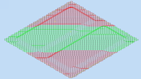
TruPlan Examples
This topic includes examples of strategy parameters and analysis modes in Autodesk Inventor. It uses the sample file MaleCoreTool.ipt found in C:\Users\Public\Documents\Autodesk\TruPlan
Open the Sample File
- In Inventor, go the TruPlan tab.
- Open the sample file MaleCoreTool.ipt.
- Click Open Composites (or Insert Composites if you already have another file open) on the TruPlan ribbon and open the MaleCoreTool.xml sample file.
-
From the Import Composites dialog box, use the browse buttons
 to open the MaleCoreTool STL files for the two surfaces of the model.
The STL file names correspond to the surfaces listed in the Import Composites dialog box.
-
In the TruPlan browser on the left side of the application window, browse to the Strategy.2 node under Overcore > Sequence.7 > Ply.7.
- Under Strategy.2, right-click Fiber Path.2 and select Visibility to show the fiber path.
- Zoom into the model as needed to see path details.
Example: Boundary Tow Overlap
- In the TruPlan browser, double-click Strategy.2.
- In the Strategy dialog box under Fiber Placement, set Boundary Tow Overlap to 50%.
- Change Boundary Tow Overlap to 0%.
Example: Course Offset
- In the TruPlan browser, double-click Strategy.2.
-
In the Strategy dialog box under Course Parameters, set Course Offset to 3mm.
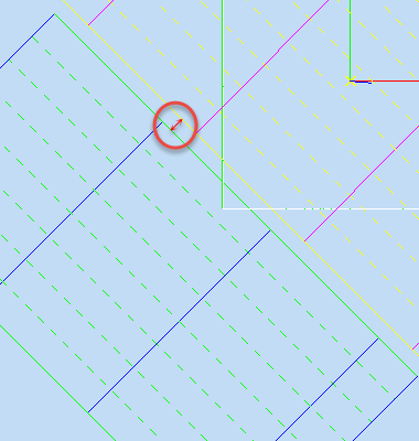
-
Change Course Offset to 0mm.
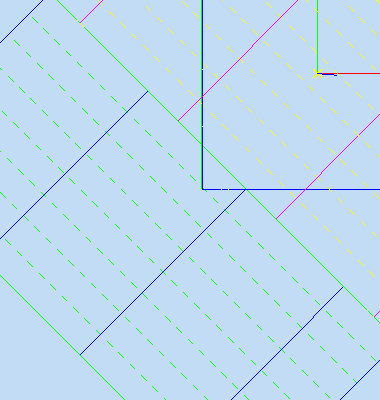
Example: Initial Course offset
Offset the first course from a seed point with a certain value. To make it easy to find the seed point in this example, it is located at the origin point of the red and green rosette.
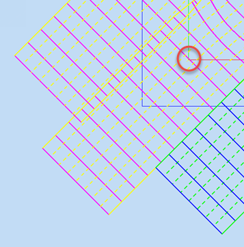
This makes it easy to compare the position of the first course to the seed point.
- In the TruPlan browser, double-click Strategy.2.
-
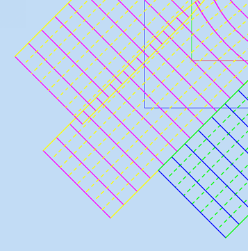
In the Strategy dialog box under Course Parameters, set Initial Course Offset to 3.175mm.
Because the material width is 6.35mm, the Overcore rosette sits exactly in the middle of a tow (between two dotted yellow lines).
-
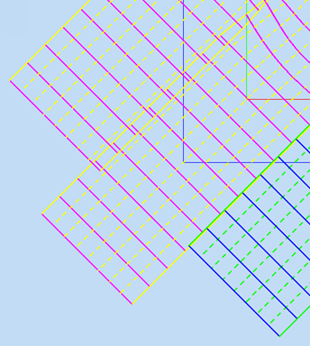
Change Initial Course Offset to 0mm.
The Overcore rosette now sits exactly on the yellow dotted line.
Example: Course Tow Overlap
Forces TruPlan to overlap adjacent courses as they are laid down. This is a percentage value between zero and 100.
- On the TruPlan ribbon, click Strategy
 .
. - In the Strategy dialog box under Fiber Placement, set Course Tow Overlap to 50%.
- Change Course Tow Overlap to 0%.
Width
Change material width in the Material Library dialog box.
-
Click Composites Library on the TruPlan ribbon.
The Material Library dialog box opens.
-
Select the Kevlar material in the Material list.
- Click the Packaging tab.
- Duplicating the 0.25in packaging.
-
Name the duplicate "0.5in" and change its Material Width to 12.7mm (0.5in).
For AFP (Automated Fiber Placement), the material width is equal to the tow width. The course width is the number of tows multiplied by the tow width. The number of tows is defined in the strategy. For ATL (Automated Tape Laying), the material width is equal to the tape width. Smaller material width eliminates much of the deviation.
-
In the TruPlan browser, double-click Strategy.2.
- In the General tab of the Strategy dialog box, select the 0.5in packing from the Material packaging box.
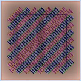
- Decrease the number of tows to four.
By doubling the material width of the tow and reducing the amount of tows by half, when using the new packaging the workpiece surface is covered by the same amount of courses.
Analysis Examples
If Analyses do not update in real-time when you change them, do one of the following:
- Right-click the analysis and select Update, or;
- Click Options on the TruPlan ribbon and select Allow Automatic Updates on the Update tab.
Analyses might be difficult to see when the workpiece surfaces are shown simultaneously. It might help to turn off the visibility of the surface geometries Overcore.1 and Plate.1 in the TruPlan browser. Disable visibility for any fiber paths or surface meshes under strategies.
Steering Example
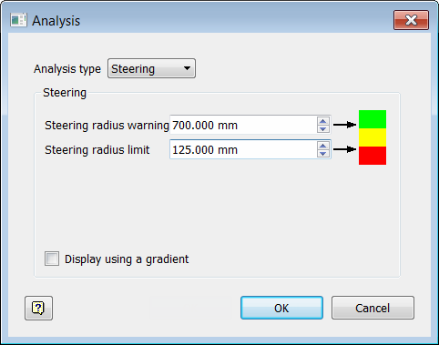
Strategy nodes contain fiber trajectories. Each trajectory is analyzed for in-plane curvature. The limits are obtained from the Steering radius warning and Steering radius limit parameters. Parts of the trajectories are colored green, yellow, or red to indicate whether the curvature is smaller than the Steering radius warning value, between the Steering radius warning value and the Steering radius limit value, or larger than the Steering radius limit value.
- In the TruPlan browser, navigate to Ply.2 > Strategy.7 > Analyses.
-
Double-click Steering Analysis.1.
The Analysis dialog box opens.
-
Look at the Steering Radius Warning and Limit values.
Flat areas (large surface curvature) are displayed in green. Areas with smaller surface curvature are displayed in yellow or even red.
Wrinkling Example
-
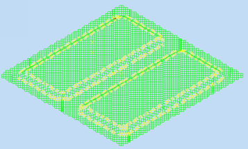
In the TruPlan browser, navigate to Ply.7 > Strategy.2 > Analyses.
-
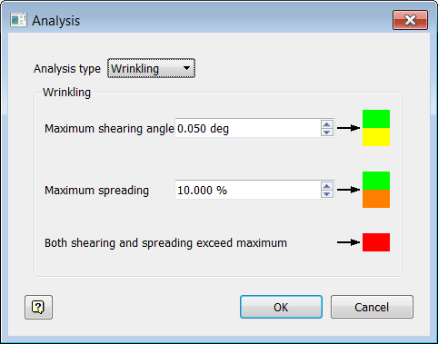
Double-click Wrinkle Analysis.1.
The Analysis dialog box opens.
-
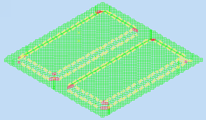
Set Maximum spreading to 2%.
Angle Example
Use this to analyze angle deviation for a given propagation mode. TruPlan calculates fiber trajectories so that the native application (for example, Inventor) can correctly interpret the fiber trajectory and determine angle deviations.
- In the TruPlan browser, navigate to Ply.7 > Strategy.2 > Analyses.
-
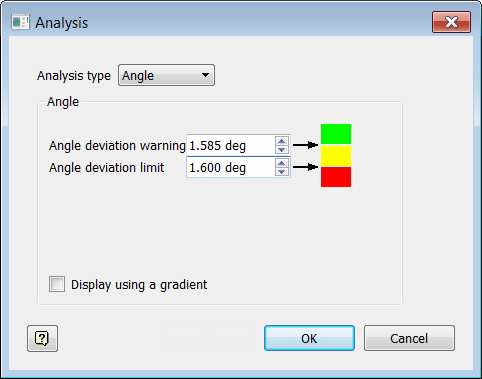
Double-click Angle Analysis.1
The Analysis dialog box opens.
.
-
Enter these values:
- Angle Deviation Warning: 1.585 deg
- Angle Deviation Limit: 1.6 deg
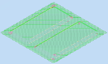
-
Make these changes to relax the limits:
- Angle Deviation Warning: 1.6 deg
- Angle Deviation Limit: 2 deg
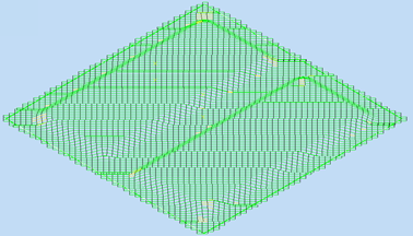
Compaction Example
- In the TruPlan browser, navigate to Ply.7 > Strategy.2 > Analyses.
-
Double-click Compaction Analysis.1.
The Analysis dialog box opens.
.
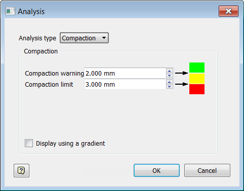
-
Look at the model.
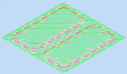
-
Enter these values:
-
Compaction Warning: 0.1mm
This is the distance after which fiber compaction affects resin infusion.
-
Compaction Limit: 1.0mm
This is the amount that the roller can deform/deflect.
-
Gap Example
Use this to visualize gaps and overlaps between courses.
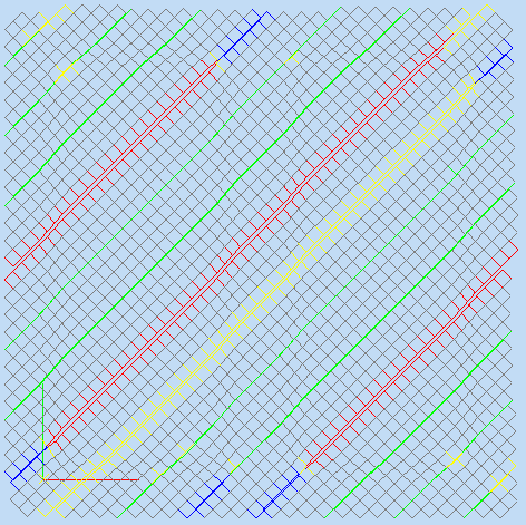
Gaps are displayed in green, yellow, and red to show Normal, Warning, and Out of Limit gaps respectively.
Overlaps are displayed in green, cyan, and blue to show Normal, Warning, and Out of Limit overlaps respectively.
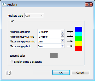
To set up the strategy for the gap analysis:
- In the TruPlan browser, double-click Strategy.2.
- Go to the Placement tab of the Strategy dialog box.
- Set Course Offset to 1mm.
- Set Optimization to Minimizing Gap.
- Set Maximum Overlap to 3mm.
To set the values for the gap analysis:
- In the TruPlan browser, go to Ply.7 > Strategy.2 > Analyses.
-
Double-click Gap Analysis.1.
The Analysis dialog box opens.
-
Set the values as shown.

-
Click OK.
- Right-click the gap analysis under Strategy.2 and make sure that Visibility is enabled.
The resulting gap analysis shows areas of overlap (blue) and excessive gap (red).
Tow Length Example
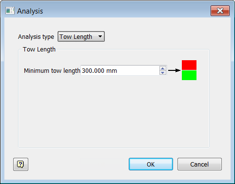
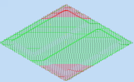
Use this to generate fiber trajectories, each of which is analyzed for the length of tows across the ply. The analysis highlights in red any areas that have shorter tow length than the defined value.
- In the TruPlan browser, navigate to Ply.7 > Strategy.2 > Analyses.
-
Double-click Min. Tow Length Analysis.1.
The Analysis dialog box opens.
.
-
Set Minimum Tow Length to 300 mm.
Tow lengths below the minimum length are highlighted in red.
-
Change Minimum Tow Length to 400in (10160mm).
