
Learn how to create and use custom connections in your 3D model.
Create a Template Connection
Before starting
Make sure all features and connection boxes related to the objects in the connection are visible.
- On the Custom connections tool palette, click
 (Create connection template).
- From the dialog box, select the appropriate definition method for the connection placement.
- According to the selected definition method, select and confirm the appropriate beams and members as prompted.
- In the User template dialog box, make the necessary settings:
- In the Name field, enter the name of the connection. This name will identify the connection in the custom connection explorer.
- Click on
 (Reselect driven/output objects) and select all objects that will be created by the connection (beams, plates, features, welds, bolts and joint boxes).
- In the Drivers selection prompts boxes, enter the desired prompts.
-
Close the dialog box.
A blue connection object appears around the template connection.
Change the Set of Connecting Elements in a Custom Connection
- Open the .dwg file containing the connection template.
- Right-click on the connection object (blue box) and select Properties from the contextual menu.
- In the User Template dialog box, click
(Reselect driven/output objects).
- Select all objects that will be created by the connection (beams, plates, features, welds, bolts and joint boxes) and press Enter.
- Close the dialog box.
- Save the file.
The blue connection object now includes the new set of selected objects.
Insert a Connection Template
- In the Custom connections tool palette, click
 (Insert connection template).
- In the Connection Template Explorer dialog box, select the desired connection. Only the files from the Connection Templates folder are displayed.
- Click OK.
- Select the appropriate elements to connect as prompted. The prompts were defined during the template creation.
The custom connection is created.
Once the connection is placed, it can be copied and grouped to efficiently place identical connections in multiple locations.
Modify a Custom Connection
- Right click on the connection object (blue box) of the custom connection to modify and select the Advance Properties from the contextual menu.
- In the User template dialog box, check the Allow object modification box.
Once the option is enabled, most parts of the connection can be edited using their individual properties dialog box.
User Template Dialog Box
Allows you to define the situation in which the connection will be used and the connecting elements of that specific connection.
| Name | Enter an appropriate name for the custom connection. Once the template connection is defined, the name appears in the Connection Template Explorer. | |
| (Reselect driven/output objects)
|
Clicking this button temporarily closes the dialog box so that you can select all objects related to the custom connection (beams, plates, features, bolts, joint boxes, etc). | |
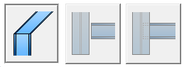
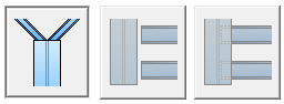
| Driver situations | Defines the situations when the custom connections will be used. The set of available options varies according to the selected definition method: | |
| One beam with end |

|
|
| One beam and point |

|
|
| Two beams |
|
|
| Three beams |
|
|
| Drivers selection prompts | Enter the desired prompts. As each prompt starts by default with "select", type only the name of the element that should be selected. | |