
You can define interactive custom connections, not available in the Connection Vault, with the desired set of connecting objects, save them and use them in your projects.
In practice, there are situations where it is not possible to use a connection from the Connection Vault. However, that situation might not be unique and you may wish to use that configuration many times in your projects.
Although custom connections are not part of the Advance Steel Connection Vault, you can store and reuse them later.
Model a Custom Connection
A custom connection is a custom combination of several basic elements drawn separately or as bricks, used to connect one, two or three profiles.
To create the custom connection template, you must model the elements to be connected by the joint and the elements that will be created by the joint. You can use any of the modelling methods available in Advance Steel:
- Include connections from the Connection Vault: create the standard connection, modify the properties as necessary.
- Custom combination of basic elements such as beams, plates, bolts, welds, cuts, copes, weld preparations, etc.
- Building bricks.
Best practices
While modelling the custom connection, ensure you use good modeling practices such as:
- Making sure system lines meet.
- Assigning model roles to all parts.
- Not numbering the parts.
Define the Custom Connection
A custom connection definition includes the connection name, the connected elements and the selection order, the set of connecting elements and (optionally) the location of the reference point to be used for aligning the connection.
You can define a custom connection using the Create connection template tool ( ), from the Custom Connections tool palette. Once the custom connection is created, you can use it in the same model or in a different one.
To define a custom connection:
- In a new drawing, manually model a typical example of the connection.
- Define the elements as connection template using
(Create connection template).
- Save the .dwg file containing the custom connection.
- Place the saved .dwg file in ProgramData\Autodesk\Advance Steel 2025\[INSTALLATION LANGUAGE EXTENSION]\Shared\ConnectionTemplates
Definition Methods
The following definition methods are available:
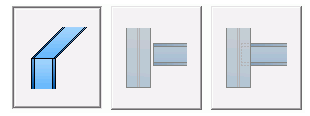
- One beam with end: used to define a connection at the end of a beam (a base plate, an end plate, etc).
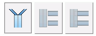
- One beam and point: used to define connections that are created at a selected point (e.g. stiffeners, reinforcement plates, gusset plates).
- Two beams: used to define connections between two beams.
- Three beams: the connection is used for one main beam and two diagonals or for one main beam and two secondary beams.
The Custom Connection Object
All connection elements and definitions in the custom connection are held together and represented as a blue bounding box (connection object).
Using the blue box you can select the connection in order to copy it, modify it or delete it.
The box can be displayed using the
 (All visible) tool from the Quick views tool palette.