
 Mesh Repair
Identifies meshes that are degenerate, non-manifold, non-oriented, self-intersecting, or that contain folded edges. The tool repairs meshes by removing the troublesome triangles.
The tests are executed sequentially, and feedback is provided through the option window and promptline after each repair step. Many tools that act on meshes such as Mesh Cut, Mesh Offset and Mesh Collar will fail on meshes that are non-manifold, non-oriented or self-intersecting. You will be asked to repair the meshes first.
Access this tool from the Mesh tool palette:
Term definitions
Degenerate: Contains duplicate triangles (that is, the same three vertices describe two triangles) , or triangles with two or three overlapping vertices.
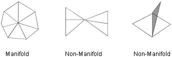
Manifold: Occurs when no vertex is adjacent to more than two boundary edges, and no edge is shared by more than two triangles.
Oriented: Refers to the winding of the vertices around the triangles is such that all normals have the same orientation.
Self-intersecting: Instances when the mesh intersects itself.
Folded edges: Instances where the angle between any pair of adjacent triangles is less than a given angle.
Mesh Repair Control settings
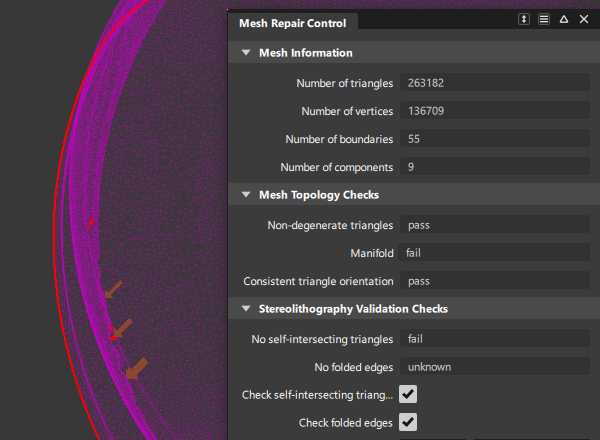
Mesh Information
Number of triangles/Number of vertices/Number of boundaries/Number of components
Non-editable fields that display information about the selected mesh.
Mesh Topology Checks
Theses checks must pass in order for other mesh tools to operate on the model.
Non-degenerate triangles/Manifold/Consistent triangle orientation
Non-editable fields that display the result of the sequential tests as pass or fail.
Non-degenerate triangles – Test passes if there are no duplicate or degenerate triangles. Also tests presence of duplicate and overlapping triangles. This happens when the same three vertices describe two triangles. This condition can be identified during test by an arrow pointing to the center of the triangles.
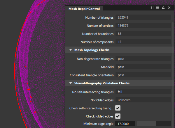
Manifold – Test passes if there are no non-manifold vertices.
Consistent triangle orientation – Test passes if the normals of all the triangles have the same orientation.
Stereolithography Validation Checks
Theses checks are only required to create a dataset that can be used in stereolithography processing.
No self-intersecting triangles
Test passes if the mesh does not intersect itself.
No folded edges
Test passes if the angle between any pair of triangles is more than the Minimum edge angle value.
Check self-intersecting triangles
If this option is checked, the self-intersecting triangles test is executed.
Check folded edges
If this option is checked, the folded edges test is executed.
Minimum edge angle
Specifies the minimum angle allowed between the planes of two triangles sharing an edge. If the angle is smaller than this value, the triangle is considered as having “folded over”. The default is 15.0 degrees.
This option is only available when Check folded edges is turned on.
Display
Display problem locations with arrows
If this option is checked, arrows point to the troublesome triangles in the mesh.
Show boundaries with arrows
If this option is checked, it displays an arrow next to each boundary at the end of the repair process. This helps to identify small and hard to detect boundaries.
Mesh Repair tool workflow
Shift-select the Mesh Repair tool.
Select a mesh.
Red arrows appear, pointing to problems with the mesh, if any. The promptline describes what type of problem the arrows represent. The control window displays mesh information (statistics) and whether or not the mesh satisfies the criteria (passes the tests) defined above. These criteria are examined, and related problems are fixed, one at a time.
If a test fails, click the Repair button in the lower right corner of the modeling window to start fixing the mesh.
Clicking the button more than once may be necessary. Alternatively, click the Repair All button to fix everything in one step.
Follow the instructions on the promptline and keep clicking the Repair button to successively correct the different problems with the mesh.
Once the process terminates, the mesh boundaries are drawn in red.
About cleaning and repairing meshes
An overview of different tools available for simplifying, cleaning, and repairing meshes.
Sometimes, a mesh might contain more triangles than are necessary to accurately represent its shape. The Mesh Reduce tool lets you reduce the number of triangles in a mesh (while attempting to preserve its shape) according to two different methods:
- Based on chordal deviation, given a maximum deviation value.
- Down to a given percentage (fraction) of the original number.
Use the Mesh Hole Fill tool to fill small holes, or holes located in an area of the mesh which is relatively flat and has no features.
Use the Mesh Patch tool to fill large holes, or holes located in an area of the mesh with features or abrupt changes in curvature. This tool fills holes in meshes while recognizing the curvature characteristics of the surrounding area. As with the Mesh Hole Fill tool, the boundary of a hole must be a closed region.
In the Mesh tool palette, click the Mesh Stitch tool
 to seal gaps between the boundaries of components in a mesh. This tool works best to eliminate narrow gaps between boundaries. To fill larger openings, in the Mesh tool palette, select Mesh Cleanup, then click the Mesh Hole Fill tool
  .
.Build small “bridges” across gaps within a mesh, so that Mesh Hole Fill
can be used to fill up the remaining holes.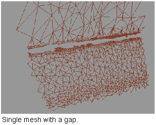
The Mesh Repair tool identifies and repairs meshes that are degenerate, non-manifold, non-oriented, self-intersecting, or that contain folded edges. The tests are executed sequentially, and feedback is provided through the option window and promptline after each repair step. Meshes are repaired by removing the troublesome triangles. Many tools that act on meshes such as Mesh Cut, Mesh Offset and Mesh Collar will fail on meshes that are non-manifold, non-oriented or self-intersecting. You will be asked to repair the meshes first.
In the Mesh tool palette, select Mesh Cleanup, then click the Mesh Weld Vertices tool
 to merge coincident vertices and average normals at the merged vertices. This tool is only needed in rare cases. For example, a file imported from a different system, in a format other than STL, could have all its shared vertices stored twice. This could be detected within the Mesh Repair tool by the presence of a red boundary surrounding each triangle. In that case, the vertices must be merged with Mesh Weld Vertices before using any other Mesh tool.
Some tools such as Mesh > Mesh Offset, require that all components of a mesh have their normals pointing in the same direction. In the Mesh tool palette, click the Reverse Mesh Orientation tool
 to work with normal directions.