 Displacement Map to Mesh
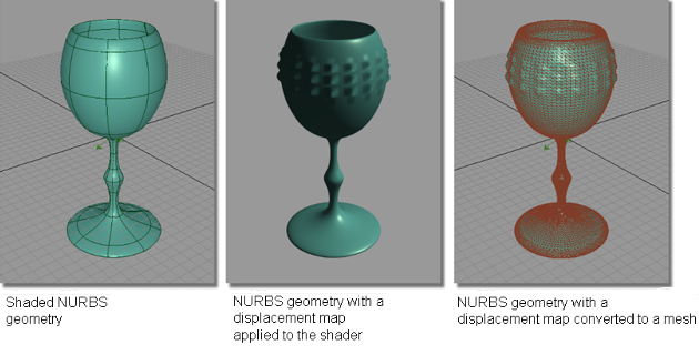
Converts a displacement map on a NURBS surface into mesh geometry. A displacement map, when placed on a surface and hardware shaded, gives the object the appearance of highly-modeled geometry, as the surface modulates based on the gray values of the displacement map.
By converting the displacement map to mesh geometry, you create real geometry that can be modified, or used in prototyping.
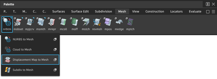
Access this tool from the Mesh tool palette:
Displacement Map To Mesh Control options
Mesh Tolerance (cm)
The maximum allowable distance (measured in centimeters) between a NURBS surface and its tessellated version, before the displacement map is applied. The Mesh Tolerance value controls how smoothly surfaces are tessellated for hardware shading.
A smoother tessellated surface results in a smoother final mesh.
The slider range is 0.001 cm to 0.10 cm. The default value is 0.05 cm for medium quality.
Displacement Detail
Controls how finely surface areas with displacement maps are tessellated. The higher the Displacement Detail value, the finer the appearance of surface displacements. The slider range is 10 - 512. The default value is 40.
Displacement Map to Mesh workflow
Assign the displacement map to a shader, then apply the shader onto the desired object(s).
Pick the object(s) with the displacement map to be converted.
Select the Displacement Map to Mesh tool
.A mesh is calculated from the displacement map, and made active. The original object is made inactive, but remains in its original location. It may be obscured until it, or the mesh, is moved.
The example below shows NURBS geometry with a procedural displacement map applied to create a “hob-nail” pattern on the outside of the plastic waterglass. Using the Displacement Map to mesh tool, the displacement tessellation is used to develop a mesh.