
Diagnostic Shading
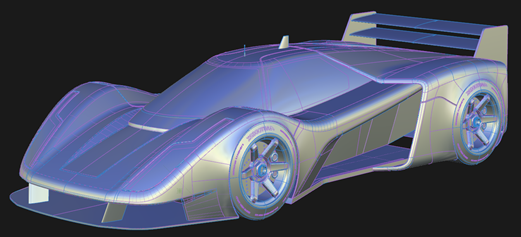
Opens the Diagnostic Shading, window provides access to various shade the model using various modes. Use the diagnostic shaders to view and evaluate your surfaces.
The various shading modes provide different diagnostic information about surfaces. Clicking a diagnostic shader icon in the window applies the shader to the selected geometry.
 Shading Off
The wireframe model appears with no shading. This icon clears the wire model of its current shading. No options are available with this shading mode.
 Multi Color
Shades all the picked surfaces with a single color. Useful for detecting bumps, dents, or other surface irregularities.
By default, Diagnostic Shading uses a point light located at the eye position of the camera. You cannot see or pick this light as an object, but you can change its parameters in the Shader Settings.
The Multi Color icon shades all the picked surfaces with a single color that you can choose. Use this shading mode to see how your model looks as a finished product, and detect any bumps, dents or other surface irregularities. You can control the shading qualities with the Light options.
 Random Color
Shades the surface with random colors. Adjacent surfaces display with different colors, making it easier to see the patch structure, and how the patches align.
You can control the shading qualities with the Light options.
The Random color mode shades the surfaces with random colors. As a result, adjacent surfaces show up in different colors, making it easier to see the patch structure, and how the patches align with one another.
 Curvature Evaluation
Color-codes the curvature of the selected surfaces. Useful for identifying where the curvature changes either abruptly or subtly and finding potential flaws.
This mode includes nine ways to view curvature. The tools color-code the curvature of your surfaces. Color-coding curvature is useful for evaluating the curvature of your model. You can see where the curvature changes either abruptly or subtly. You can also find potential flaws.
 Iso Angle
Displays highlights from a light source (single or multiple light beams).Use this shading mode to help identify where the reflected light does not move smoothly.
See Diagnostic Shader Workflows.
Iso Angle highlighting helps you find surface flaws. A common use for Iso Angle is to identify adjacent surfaces with mismatched tangents in other words, surfaces that do not meet smoothly. You can also use Surface Continuity for this purpose, but Iso Angle gives you a clearer view of the surfaces.
Through a light source manipulator, this mode lets you sweep beams across a surface. You can see where the reflected light does not move smoothly. A jump in the reflection indicates flaws in either the surface or its boundary with a second surface.
Single, double, multiple (red, black, and white) or rainbow map type can be used.
 Horizontal/Vertical
Displays horizontal or vertical highlights on the surface. Useful for identifying surfaces that do not meet smoothly or have mismatched tangents.
Horizontal/Vertical highlighting helps you find surface flaws. A common use for this is the identification of adjacent surfaces with mismatched tangents, in other words, surfaces that do not meet smoothly. You can also use Surface Continuity for this purpose, but Horizontal/Vertical highlighting gives you a clearer view of the surfaces.
This mode lets you sweep multiple black and white highlights across a surface. You can see where the highlights do not move smoothly. A jump in the highlight flow indicates flaws in either the surface or its boundary with a second surface. You can control the shading qualities with the Light options.
 Surface Evaluation
Displays the model using Draft Angle, Deviation Map, or Contact Analysis shading. Use this to shade a surface with its draft angles create curves-on-surface with the shader data.
See the following:
- Diagnostic shader workflows
- About shading with draftangles
- Create curves-on-surface with Evaluation shaderdata
 User Defined Texture
Displays a user-defined texture reflected on the selected surfaces. Use one of the default textures or load one of your own in the Shader Settings.
See Shader Settings.
You can control the shading qualities with the Light options
 Light Tunnel
Creates linear reflections on the model by surrounding it in a cylindrical tunnel of long lights. This shader has the same functionality as in the Hardware Shade Environment.
 Clay
Clay
Gives the model the look of clay by shading it with a low specularity clay color. This shader supports the display ambient occlusion, but you must first calculate ambient occlusion to see the effect.
 Isophotes
Displays thin, sharp lines to indicate spots of the same brightness (isophotes). This is useful for detecting discontinuities across surfaces.
 VRED Nurbs Analysis
Sends the current model to VRED NURBS Analysis to perform ray tracing directly on the NURBS surfaces. You can display different types of virtual lines on the objects in the scene to examine the continuity of surfaces.
 Visual State 1, 2, and 3
Turns on hardware shading and shades the model using the environment and shading settings associated with the tool. The settings are stored with your user preferences.
Click one of the three Visual State buttons to turn on hardware shading and shade the model using the environment and shading settings associated with the button.
You can change the settings associated with each of these buttons by clicking the button preset you want to change and using the Visual State options. The settings for the three Visual State buttons are stored with your user preferences.
 File State
Shades the surfaces using the last active environment that was saved when you last saved the file. The settings for the last active environment are stored with the File State button when you save your file.
The settings are saved with the file, so anyone opening the file can set the environment to your last active environment using this button. You can change the settings associated with the File State button by clicking the button and using the File State options. Save the file to save the new settings with the button.
 Box Mode
Shades the subdivision control cage in a flat default material. This shader is useful for detecting surface quality problems such as odd-sized faces, zigzagging edge loops, or other surface irregularities.
Box Mode has no effect on NURBS surfaces.
Global Settings
Tolerance
Controls how accurately surfaces are tessellated when Tessellator is Fast. The slider range is 0.01 to 10.0. The default value is 0.1.
As the value increases, the accuracy of the triangulation decreases. When set to to 0.1, the surfaces of the model become completely shaded because the triangulation is more accurate, however, the process takes longer. Choosing a tolerance value means balancing time versus appearance.
Tessellator
Sets the method used to approximate the surface as a collection of polygonal objects.
Fast – Tessellates more quickly and less accurately.
Accurate – Tessellates more accurately and more slowly. When set to Accurate, an additional Limit Edge Length option appears. Turn this option on, and then use the Max. Edge Length slider control to set the maximum length (in current units) of a triangle created by tessellation.
Shade New objects
Automatically shades new geometry created by tool operations with the currently assigned diagnostic shader. New objects is on by default.
Shader Settings
The diagnostic shader settings are listed in alphabetical order.
Ambient Light
(applies to the Horizontal/Vertical and User-Defined Texture shaders) Slide to set the level of ambient light, an illumination that comes from all directions and lights all objects uniformly. The slider ranges from 0.0 (no illumination) to 1.0 (maximum illumination).
Band Fringe
(applies to the Light Tunnel shader) Controls the edge transition of lights, ranging from a hard, sharp transition to a smooth, soft transition.
Band Width
(applies to the Light Tunnel shader) Controls the width of the light bands.
Base Color
(applies to the Isophote shader) Use the slider control to set the of the model.
Blur
(applies to the Iso Angle shader) The blurriness of iso-angle line edges.
Center Tunnel
(applies to the Light Tunnel shader) Centers the tunnel at the origin.
Color
(applies to the Multi Color shader) Click the color swatch to set the color, or drag the slider to change the color’s brightness.
Color Saturation
(applies to the Random Color shader) Sets the common saturation, or the “vividness”, of the color.
Count
(applies to the Isophote shader) Controls the number of isophote lines used.
Curvature Evaluation Type
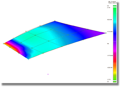
(applies to the Curvature Evaluation shader) The Curvature Evaluation Type settings listed in the image calculate the curvature of surfaces on each point. This calculation measures the diameter of a circle that touches the surface at each point. Points that have a circle with the same diameter are displayed with the same color. Each point can have several circles. The Curvature Evaluation Type settings specify which circles are used for the calculation.
Crv V, Crv U
Display the curvature in the surface’s V or U parameter direction at each point.
Crv Z, Crv Y, Crv X –
Display the curvature in the Z, Y, or X direction at each point.
Mean
Use the average of the two principal curvatures to approximate the average curvature through each point.
Gaussian
Use the product of the two principal curvatures.
Princ. Min
Use the minimum curvature values (that is, the curvature of the flattest curves that pass through each point).
Princ. Max
Use the maximum curvature values (that is, the curvature of the steepest curves that pass through each point). In the image below, the surfaces, or areas of surfaces that fall below the defined radius limit are highlighted in red through the Princ. Max setting.
Curvature Color Scale
(applies to the Curvature Evaluation shader) Scales the radius ramp to show finer details of curvature variation.
Curve Control
(applies to the Iso Angle and Surface Evaluation shaders) Controls whether Visual curves-on-surface are created from iso-angle lines, or actual CoS curves-on-surface. The latter can be used for modeling operations such as geometry creation, trimming, or measuring.
Show Curves Only
Disable the shading and show the iso-angle lines as curves only.
Create
Create iso-angle curves.
Delete
Delete iso-angle curves.
Diffuse Light
(applies to the Horizontal/Vertical and User-Defined Texture shaders) Slide to set the ability of objects to reflect light in all directions. The slider ranges from 0.0 (no light is reflected) to 1.0 (all light is reflected).
Environment Editor
(applies to the Visual State and File State shaders) Click this button to adjust the environment settings in the Environment Editor.
Highlights
(applies to the Multi Color shader) When set to Fast, the highlights are calculated more quickly and less accurately. When set to Accurate, the highlights are calculated more accurately, but more slowly.
Intensity
(applies to the Light Tunnel shader) Controls the relative brightness of the reflections. Values greater than one are equivalent to setting a light to the same intensity.
Layer
Choose a shader from this menu to layer on top of an already applied diagnostic shader. Choose between Isophotes, Curvature, or Horiz/Vert. The default is None.
The parameters of the layered shader appear in the Layered Properties section below the parameters of the original shader in the control window.
Light Azimuth
Azimuth values range from -180 degrees to 180 degrees and rotate the light horizontally.
Light Elevation
Elevation values range from -90 to 90 degrees and rotate the light vertically.
The following options apply to Multi Color mode only.
Light Intensity
Set the brightness of the light source.
Link Light to Camera
When this option is checked on (default) the light source for the shading comes from the camera like a headlight, so that the highlights move over the model as you tumble around it.
Checking off this option un-links the light source from the camera and locks it to its current position, so the highlights remain stationary as you tumble. It also displays two sliders and a manipulator that let you rotate the light around the model.
Alt + Shift + left mouse button, with Tumble Center set to World Point in View > World Move Camera > Tumble. Setting a point-of-interest (POI) on the geometry or doing a View > Look At modifies the tumble center, hence the center of rotation.Lock Texture
(applies to the Horizontal/Vertical and User-Defined Texture shaders) Normally the highlights are projected from the camera, so the projection changes as you move around the surface. This is the unlocked mode. You can turn this option on so that the texture remains locked relative to the surface.
Map Type
Available Map Types depend on the selected shader.
For the Iso Angle shader this option controls how the iso-angles lines display.
Single – Displays a single black and white iso-angle line.
Double – Displays a wide iso-angle line.
Multiple – Displays red, black, and white iso-angle lines.
Rainbow – Displays bands corresponding with each color of the rainbow.
For the Horizontal/Vertical shader this option controls how the iso-angles lines display.
- RB Vert, RB Hor - Sets the vertical or horizontal highlights to RGB colors.
- BW Vert, RW Hor - Sets the vertical or horizontal highlights to black and white. Use the Color slider controls to adjust the color values or click the Color swatch to pick a color. You can also controls the thickness of the bands inside the texture by adjusting the Thickness slider control.
For the User-defined Texture this option controls how the iso-angles lines display.
Showroom – Shows a texture map with a showroom reflection.
Photo-Horizon – Shows a texture map with a photo-horizon reflection. The abstract Photo-Horizon ramp produces a high contrast effect often used in stylized sketching.
Diffuse – Shows a texture map with a diffuse reflection. The abstract Diffuse ramp provides low contrast reflections appropriate for studying overall form and volumes.
Shade-Sky – Shows a texture map with the reflection of the sky.
Double-horizon – Uses two reflective highlights, as though the model was reflecting a double-horizon.
User defined – Choose your own reflected texture.
Max. Radius Limit
(applies to the Curvature Evaluation shader) Surface regions having a radius larger than the Max. Radius Limit value are indicated by one color, and surface regions having a radius less than the Max. Radius Limit value are indicated by a different color.
This option is only available for the Princ. Min Curvature Evaluation Type.
Min. Radius Limit
(applies to the Curvature Evaluation shader) Surface regions having a radius less than the Min. Radius Limit value are indicated by one color, and surface regions having a radius greater than the Min. Radius Limit value are indicated by a different color.
This option is only available for the Princ. Max Curvature Evaluation Type.
Number of Bands
(applies to the Iso Angle shader and Light Tunnel) For the Iso Angle shader it controls the number of times colored band iso-angle lines are repeated on each surface. This option is only available if Type of Bands is Multiple. For the Light Tunnel shade, it controls the number of light bands used to form the tunnel.
Reflections
(applies to the Multi Color shader) When on, the following Reflections options are displayed.
Reflectivity
Use this slider to control how much your model reflects the scene.
Scene
Choose a reflection map by clicking Scene for a drop-down menu. The choices are Showroom, Hall, Evaluation, Diffuse, and Abstract.
Scene imagery by CGI Backgrounds: http://www.cgibackgrounds.com/.
Sky environments images copyright © 2004 Dosch Design GmbH. For more textures, 3D models and HDRIs, please visit http://www.doschdesign.com.
Show Orientation
(applies to the Multi Color shader) When Mode is set to Visual, components of surfaces or meshes that have reversed normals are shaded in yellow. When set to Geometric, reversed geometric normals are shaded in red.
Repeats
(applies to the Horizontal/Vertical and User-Defined Texture shaders) Sets the rate at which the texture repeats. Increasing this number will increase the number of highlight lines on the surfaces.
Save To Prefs
(applies to the Visual State shaders) Click this button to save your changes to your user preferences.
Shade Settings
(applies to the Visual State and File State shaders) Click this button to adjust the hardware shading settings in the Hardware Shade window.
Sharpness
(applies to the Isophote shader) Controls the sharpness of the isophote lines. increasing the value blurs the line edges.
Show Manip
Displays the diagnostic shader manipulator, which you can use to position and scale entities, such as highlights or the light tunnel.
Show Occlusion
If ambient occlusion has been calculated, displays the resulting shadow textures on the shaded model.
Concentration
Increase this value to cause the occlusion shadow to be more concentrated in the areas where it is darkest.
Contrast
Set how dark an area with ambient occlusion is. When the value is 1, areas with maximum ambient occlusion are rendered as if there is no ambient light.
Show Tunnel
(applies to the Light Tunnel shader) Displays the tunnel, representing the lights as green bands.
Specularity
Change the size and intensity of highlights on the surface.
Stripe Color
(applies to the Isophote shader) Choose a color for the isophote lines.
Subdivision only
(applies to the Box Mode shader) Lets you isolate the shader's effect to subdivision bodies only. For example, if your scene includes both NURBS surfaces and subdivision objects, only the subdivision objects are shaded in BoxMode. This option is on by default.
Surface Evaluation Type
(applies to the Surface Evaluation shader) Choose between Draft Angle, Deviation Map, or Contact Analysis shading types.
Draft Angle
Some manufacturing processes, like injection molding, need you to design molds. A section of a mold only moves in a certain direction during removal. This direction is the pull vector.
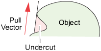
- The mold parts are pulled away from the object in a straight line, the pull vector.
- If the sides of the mold are too steep, the object cannot leave the mold. As well, the object cannot leave the mold if the mold undercuts itself.
- The minimum allowable angle between the sides of the mold and the pull vector is the draft angle.
- If part of a surface has an angle less than the draft angle, it is said to be out-of-draft.
- Draft lines are the boundaries between in-draft and out-of-draft regions.
- The parting line sits at a draft angle of zero degrees, and corresponds to the location where the mold separates.
Angle-to-pull is the angle between the surface tangent plane at a surface point and the pull vector. When the angle-to-pull is 0 degrees, the pull vector is parallel to the surface tangent plane at that point. When the angle-to-pull is 90 degrees, the pull vector lies normal to the surface.
Most manufacturing processes require that the angle-to-pull for a molded surface be greater than some angle, for example 1 degree, or else the molded part will not separate from the mold. This angle is the draft angle.
When the angle-to-pull is less than the draft angle, the surface point is out-of-draft. When the angle-to-pull is more than the draft angle, the surface point is in-draft.
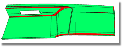
The Draft Angle shading mode offers the ability to evaluate in-draft and out-of-draft regions along both directions of the pull vector, since a mold often separates in both directions. Positive and negative in-draft and out-of-draft regions of the surface, as well as tolerance regions are shaded different colors. Tolerance regions are "grain wash" zones that forms part of the out-of-draft regions.
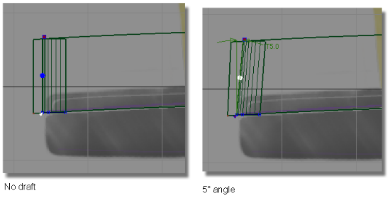
In the pictures above, the draft surface is angled in to the pull direction by 5 degrees. This angle allows the model to be withdrawn from the injection mold.
In-draft points are shaded blue or green, while out-of-draft points are shaded red. You can also display tolerance regions in cyan and yellow through the Pos Tolerance and Neg Tolerance number fields.
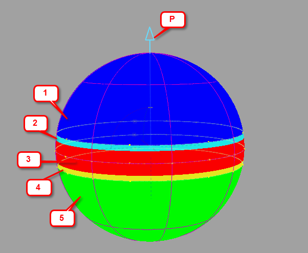 Output from Draft Angle diagnostic shading showing the different shaded regions.
- p - Pull direction
- 1 - Positive in-draft region
- 2 - Positive tolerance region
- 3 - Out-of-draft region
- 4 - Negative tolerance region
- 5 - Negative in-draft region
These shading options display which parts of a surface are in-draft or out-of-draft for one or both directions of a specified pull vector, and associated draft angle(s). These options appear when you set Type to Draft Angle:
Positive Draft - Check on this option if you want to see the in-draft and out-of-draft regions for a given draft angle (Pos Draft Angle) with respect to the given pull vector.
Pos Draft Angle - If the angle between a surface point and the pull vector is less than this value, the surface point is out-of-draft, and is colored red. If the angle between a surface point and the pull vector is more than this value, the surface point is in-draft, and is colored blue.
Pos Tolerance - Displays a cyan tolerance region between the positive in-draft and out-of-draft regions. The tolerance value represents an angle measured in degrees. If the tolerance value is 0, no tolerance region is displayed.
Negative Draft - Check on this option if you want to see the in-draft and out-of-draft regions for a given draft angle (Neg Draft Angle) with respect to the negative (opposite) direction of the pull vector.
Neg Draft Angle - If the angle between a surface point and the direction opposite to the pull vector is less than this value, the surface point is out-of-draft, and is colored red. If the angle between a surface point and the direction opposite to the pull vector is more than this value, the surface point is in-draft, and is colored green.
Neg Tolerance - Displays a yellow tolerance region between the negative in-draft and out-of-draft regions. The tolerance value represents an angle measured in degrees. If the tolerance value is 0, no tolerance region is displayed.
Show Pull Direction At - See Vector Controls.
Curve Control - See Curve Control.
Zero Degree - Turn on this option to create a curve on the surface for a draft angle of 0 degree. This corresponds to the location where the mold separates.
Show Curves Only - This option is only available if Create Curves is checked on. Disables the shading and shows the draft lines as curves only.
Subdivision - The quality of the curve-on-surface projection, from 1 to 6. The higher the value, the more precise the result. Use low values for draft quality, use higher values for final results.
Tolerance - When Visual is selected, this value defines the quality of the visual curves independently of the tessellation tolerance. This lets you set the visual tolerance to a smaller value to get better quality visual curves, without reducing the tessellation tolerance used for shading.
Contact Analysis - needs description
Deviation Map - needs description
Thickness
(applies to the Horizontal/Vertical and Isophote shaders) For the Horizontal/Vertical shader it controls the thickness of the bands inside the texture when the Map Type is set to BW Vert or BW Hor.
For the Isophote shader, it controls the thickness of the isophote lines.
Transparency
Sets the transparency value of the shaded surfaces, from 0.0 (totally opaque) to 1.0 (totally transparent).
Use bands
(applies to the Curvature Evaluation shader) When this option is turned on, the ramp displays solid bands of color instead of slowly varying colors. This option is not available when Min. Radius Limit or Max. Radius Limit are turned on.
Use Camera View Vector
(applies to the Isophote shader) Uses the current camera view vector for the light direction so the lines move over the model as you tumble.
When this option is not selected, the lines remained fixed.
X, Y, Z
Sets the position of the light when Use Camera View is not selected.
Vector Controls
(applies to the Iso Angle and Surface Evaluation shaders) The position of the vector represented by the arrow icon (light source).
X, Y, Z
Aligns the light source vector with the X, Y or Z axes.
Update From Selection
Set the direction of the light source to be that of an already selected vector or plane. In the case of a plane, the direction perpendicular to the plane is used.
Width
(applies to the Iso Angle shader)The width of white band iso-angle lines. This option is only available if Type of Bands is Single.
Diagnostic Shader workflows
Set the shaded color
Pick the surface or surfaces.
The options appear at the bottom of the Diagnostic Shade window.
Click the color swatch to show the color editor.
How does setting the color in Multi Color mode affect objects?
- If you have picked objects, you will set the color of those objects. This only sets the color shown in this shading mode. It does not affect the rendered appearance (shader) of the objects.
- If nothing is picked, you will set the color of all objects, even objects to which you have already assigned custom colors. If you accidentally reset your colors, use Undo.
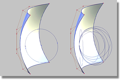
Show iso-angle lines on a surface
Iso-angle projects onto the surfaces from a certain angle, and creates shaded bands and/or lines where the surface is at right angles to the projection direction.
Pick the surfaces and click the Iso Angle diagnostic shader icon
in the Diagnostic Shade window.From the Map Type drop-down menu, choose whether to shade with a single band, double, multiple, or rainbow bands.
Adjust the number, blur and transparency of the shaded bands.
Under Curve Control, choose whether to display iso-angle lines as actual curves-on-surface (CoS) geometry or display only (Visual) curves-on-surface and click Create.
To remove the shading and view the curves only, select Show Curves Only.
Use the manipulator to set the direction of projection.
If the manipulator is not visible, click the Show Manip button.
Tip: It is often helpful to use multiple bands as you position the manipulator to give you more feedback, then switch to fewer or a single band.
Shade a surface with its draft angles
Click the Surface Evaluation shader icon
in the Diagnostic Shade window.Click the small triangle (as shown below) to display the shading options.
In the Type pop-up menu, choose Draft Angle.
Choose whether to specify the pull direction as a rotation (from the normal “up” direction) or as a vector, then enter the X, Y, and Z values.
Note: If you want to use an existing vector or plane to specify the pull vector, pick it, then click the Update From Selection button. This automatically sets the X, Y, Z coordinates to the correct values in the window.Check or uncheck the Positive Draft and Negative Draft check boxes depending on whether you want to see the draft angle data along one or both directions of the pull vector.
Do any of the following:
- Set the positive and/or negative draft angle(s).
- Set the positive and/or negative tolerance angle(s) to show the tolerance region(s) between in-draft and out-of-draft regions.
- Adjust the transparency of the shader.
The shading updates on your objects. You may see up to five colors, as shown bellow.
- Use the Construction Vector
 tool to create a reference vector, and point it in the direction you want.
 - Pick the reference vector and click the Update From Selection button under the Draft Angle options in the Control Panel. If you pick a plane instead, then the direction perpendicular to the plane is used.
The X, Y, and Z coordinates of the vector are automatically set.
Move the light around the diagnostic shaded objects
The following diagnostic shaders let you unlink the light from the camera position:
- Multi-Color
- Random Color
- Horizontal/Vertical
- User Defined Texture.
When you choose one of these shading modes in the Diagnostic Shading window, and clear the Link Light to Camera option, a white sphere manipulator appears in the perspective window. Clicking and dragging this manipulator moves the light interactively around your model.
Azimuth and Elevation sliders also appear in the Diagnostic Shade control window, and update in synch with the manipulator. Use them to enter exact values, or for fine tuning.
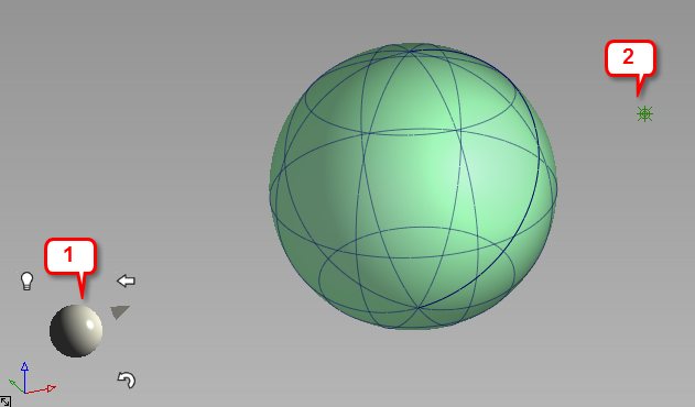
1: Light manipulator. 2: Light icon
Use the light manipulator
Click and drag the manipulator.
- Dragging horizontally changes the azimuth of the light.
- Dragging vertically changes the elevation of the light.
A point light icon represents the light in your model. Depending on the position of the camera with respect to the light, the light icon is not always visible. The light icon is toggled off by default.
Click one of the three icons surrounding the manipulator to do the following:
![]()
A. Curvy arrow: Reset the light to the camera position. Clicking this icon also sets the "home" view, as well as a new pivot location for the light to rotate around. The pivot location is the pivot point, if one exists, or tumble point otherwise.
B. Left pointing arrow: Reset the perspective view to the "home" orientation.
C. Light bulb: Toggle the light icon on and off. It is off by default.
About shading a surface with its draft angles
Some manufacturing processes, like injection molding, need you to design molds. When a mold is used it is pulled away from the finished part along a pull direction, and sometimes in two opposite directions simultaneously .
The Surface Evaluation option of the Diagnostic Shade window allows you to shade the picked surfaces with a color map showing areas in and out of draft for checking mold manufacturability.
This shading mode shows you which parts of a surface are in-draft and out-of-draft for both directions of a specified pull vector (since a mold often separates in both directions) and for positive/negative draft angles. Positive and negative in-draft and out-of-draft regions of the surface, as well as tolerance regions, are shaded different colors. Tolerance regions are "grain wash" zones that form part of the out-of-draft regions.
You can generate the draft angle shading by using diagnostic shading.
You can also create curves-on-surface (or just visual curves) along the draft lines and parting line.
Terminology
- Angle-to-pull is the angle between the surface tangent plane at a surface point and the pull vector.
- When the angle-to-pull is 0 degrees, the pull vector is parallel to the surface tangent plane at that point.
- When the angle-to-pull is 90 degrees, the pull vector is normal to the surface.
- Most manufacturing processes require that the angle-to-pull for a molded surface be greater than some angle, for example 1 degree, or else the molded part will not separate from the mold. This angle is the draft angle.
- When the angle-to-pull is less than the draft angle, the surface point is out-of-draft.
- When the angle-to-pull is more than the draft angle, the surface point is in-draft.
Create curves-on-surface with Evaluation shader data
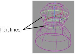
Create curves-on-surface from parting line data
To create curves-on-surface along draft lines (boundaries of out-of-draft areas) as well as the parting line (0 degree line) given a pull direction.
Pick the surfaces on which you want to create curves-on-surface.
Optionally, pick a vector object to use as the pull vector (see Construction > Vector).
Click the Surface Evaluation diagnostic shader
in the Diagnostic Shade window.Decide if you need to see the draft lines for both directions of the pull vector, or only one direction, and adjust the Positive Draft Angle and/or Negative Draft Angle accordingly.
Use the Vector Control options in the Diagnostic Shade window to change the pull direction.
Modify the following options if needed:
- Positive Draft Angle and/or Negative Draft Angle
- Under Curve Control select CoS for geometry curves-on-surface or Visual for display only curves-on-surface.
- Parting line Zero degree (on or off)
- Subdivisions (quality of the curves-on-surface – you can type in a value higher than 6).
Click the Create button at the bottom of the Diagnostic Shade window to create the curves-on-surface, click the Delete button to remove them.
You can also use shading to display the in-draft and out-of-draft areas in addition to tolerance zones, by turning on Shade Surfaces.