
Fills the space under the supported area with arrays of bars
 Previously called
Area with bar support
Previously called
Area with bar support
Jump to:
- General parameters
- Anchors
 Groups
- Bundle into bouquets
- Root system
- Project bar
- Brace
- Support properties Baseplate
General parameters
| Parameter | Explanation | Notes |
|---|---|---|
| Description |
Provide a custom name to identify the support action at a glance. Particularly helpful when you have the same action multiple times for a staggered approach to supporting parts. |
|
|
Color
|
Sets a display color for the support elements generated by this action |
Cannot be reverted once changed, only explicitly set to a new color |
| Cluster |
Search parameters for areas of contiguous triangles requiring supports |
|
| Anchors |
Parametrization of the arrangement of connection points along cluster areas |
See Anchors |
|
Groups
|
Forms groups of bars for optional cross-bracing, bunching with a tapering envelope, and generating local baseplates |
See Groups |
| Bundle into bouquets |
Collect bars into tree-like structures |
|
| Root system |
Add bracing bars to the lower end of a support bar |
See Root system |
| Project bar |
Deflect bars to avoid or prefer part-to-part connections |
See Project bar |
| Maximum bar height |
After sprouting from the supported downskin, bars are at most this long, measured along Z, regardless whether they connect to anything at their bottom end. |
|
|
Brace
|
Generates cross-bracing bars between bars in a group |
See Brace |
| Support properties Bar |
Parametrization for the shape of the bars generated by this action |
|
|
Support properties Baseplate
|
Parametrization for the shape of local baseplates generated for grouped bars |
Anchors
| Parameter | Explanation | Notes |
|---|---|---|
| Anchor distance |
Defines the space between two anchor points or bars |
|
| Contour offset to wall |
Anchors keep a distance from a cluster contour that borders a wall (a concave border). |
|
| Free contour offset |
Anchors keep a distance from a cluster contour that does not border a wall. |
|
| Down-oriented points |
Adds a single bar to local minima within a cluster |
|
| Corners |
Places bars in sharp corners first. Helpful to ensure support to corners in case the interval between area or border bars happens to leave them out. |
|
| Add bars to medial axis |
Adds a single row of bar supports to a stretch of supportable area where that stretch would otherwise be too narrow to be eligible under the given, regular contour offset. |
|
| Medial axis contour offset |
Adds the bars to eligible area stretches only if the stretch is at least twice this wide. |
Unavailable unless Add bars to medial axis is set to Yes |
| Borders |
When set to No, the cluster's contour is left unsupported |
|
| Rasterize area |
When set to No, the cluster's area is left unsupported |
|
| Anchor alignment |
Switches between rectangular and hexagonal anchor placement for area-filling bar support |
Unavailable unless Rasterize area is set to Yes |
|
Alignment origin
|
On cluster (default): For each individual cluster found and filled by this action, the area-filling pattern of anchors is individually aligned. Global: The area-filling pattern of anchors across all clusters found and filled by this action are commoned, trading a potentially less fitting alignment for potential benefits during beam path exposure |
|
| Z range limitation |
Even when a downskin cluster spans a greater height range than given by Minimum Z value and Maximum Z value, only those anchors sprout bars that lie within the values specified here. |
Groups
There is no explicit switch to turn grouping off. It is technically always active, but as long as no tapering, bracing, or generation of a local baseplate is specified, it has no effect.
| Parameter | Explanation | Notes |
|---|---|---|
| Bars per group |
Bunches at most this many bars into a group. A group of bars may receive braces, may have a local baseplate, and the group as a whole may be tapered. |
|
| Group taper |
Controls the taper of a group of bars
|
Unavailable while Bars per group is <2 or Number of legs is >0 |
| Baseplate for group |
Adds a local baseplate to a group's contact point or patch on the platform |
Unavailable while Number of legs is >0 |
Pad height,
Contour offset,
Taper angle, or their equivalents, have been moved to the separate
Support properties Baseplate section.
Bundle into bouquets
| Parameter | Explanation | Notes |
|---|---|---|
| Bundle into bouquets |
When active, bars are merged into trunks before reaching their lower end on part or platform. |
|
| Bouquet diameter |
Defines the maximum diameter of single bouquet structures. Smaller diameters cause creation of more, and smaller, bouquets. |
|
| Bouquet height |
Enforces a minimum distance between the first branch of a bouquet structure and the part. |
|
| Recursive depth |
Sets the limit of branches per bar between the first branch and the part. |
|
| Bouquet type |
Anchor on bar picks one main bar and grows additional bars from it or from other bars that originate on the main bar themselves ("side branching"). Free anchor uses iterative splitting of bars into ever thinner ones to ultimately cover the cluster's entire surface area with supports ("split branching"). Side branching
Split branching
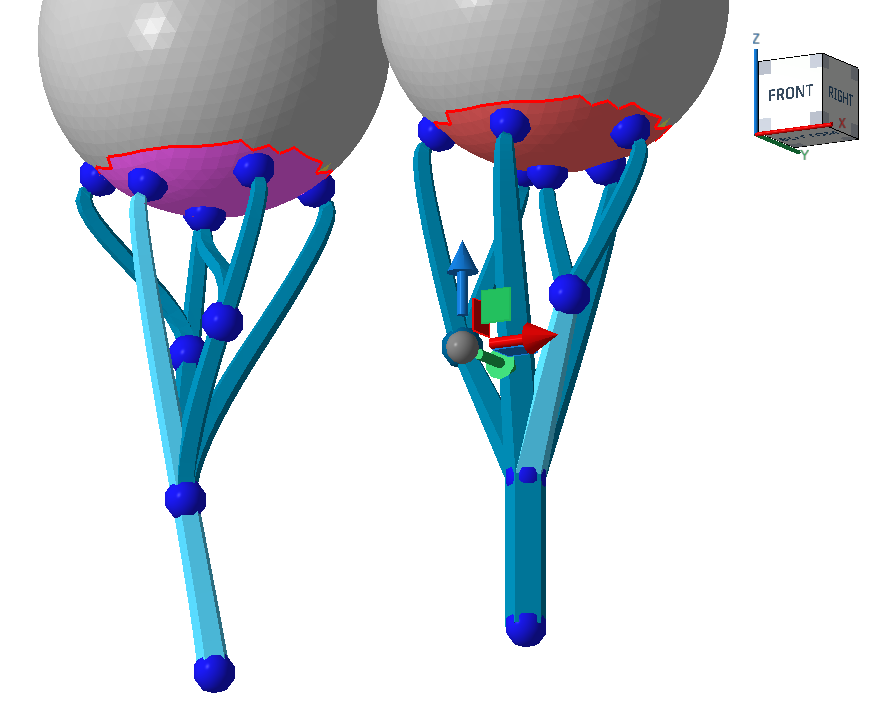 Side branching (left) and split branching (right). Note how the selected one on the left goes all the way from the part surface to the bottom, and how other beams "sprout" from it, whereas on the right, the branches split evenly. |
|
| Maximum bar gradient |
Ensures that no bar in a bouquet ends up angled further away from the vertical than this threshold even when the parameter height and diameter would permit it. If necessary, the bouquet height is increased beyond Bouquet height, and if this is not enough, a new bouquet is started. If that's not possible either, the bar is projected as an individual one as usual. |
Root system
When active, the bottom of the bars are multiplied to form a tree-root-like structure that reinforces the adherence of individual bars.
| Parameter | Explanation | Notes |
|---|---|---|
| Number of legs |
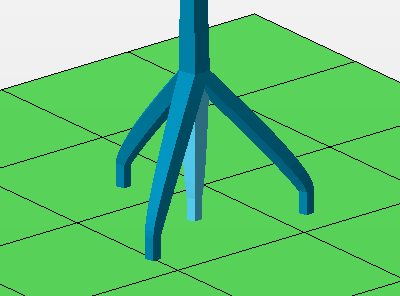 The count of legs includes the center one. |
|
| Height |
At this height above the platform or the bottom part surface, measured along the center leg, the side legs merge with the main bar. |
|
| Diameter |
The legs terminate at a circular contour of this diameter parallel to the build platform. If the bars meet a suitable surface before or beyond this imaginary circle, such as when they terminate on an uneven part surface, the bars are shortened or extended appropriately to maintain the side bar angle. |
Project bar
| Parameter | Explanation | Notes |
|---|---|---|
| Snapping on intersection |
Controls whether bars that fractionally intersect with the part surface should redirect to properly terminate on the surface or ignore and continue to reach to their regular end point on platform or part. |
|
| Project bar |
Controls angling bar support entities to preferably hit or avoid part surface. Options
|
|
| Maximum projection angle |
When a bar support entity is eligible for angling, Netfabb attempts to angle (up to a specifiable maximum) and pan the bar to terminate it on the desired part or platform surface. If no suitable angle or panning is found, the bar is projected vertically as usual. |
|
| Surface normal for direction |
To find the final angle of a bar support entity, the surface angles on both ends of the bar are taken into account. Using this percentage value, you adjust the weighting of either surface angle in the calculation of the bar's angle between 0 % (the vertical) and 100 % (the downskin angle). Note: The
maximum projection angle still applies.
|
 Upskin projection
 Brace
| Parameter | Explanation | Notes |
|---|---|---|
| Brace |
Arrangement and orientation of the cross-bracing bars given by the capital letters resembling the shape |
|
| Links per bar |
A bar in a group may be linked to up to this many other bars by cross-bracing |
|
| Link angle |
Lowest angle against the horizontal for the cross-bracing bars |
|
| Junction shape |
Adapts or overrides the type of junction that the cross-bracing bars use to transition into the bars they connect between. For example, while the main bar may prescribe a straight connection in Support properties, any connecting bars generated out of bracing could still have straight connections. |
|
Support properties Baseplate
These local baseplates generate for groups of bars when is set to Yes. These baseplates are distinct from .
| Parameter | Explanation | Notes |
|---|---|---|
| Outer offset |
Distance by which the minimum contour formed by the contact points of a group's bars is extended to make the base plate's contour. This is the minimum distance before tapering. For the Pattern of Point connection net, no offset is generated. Instead this value is used to derive the wall thickness of the point connections, using effectively twice this value. |
|
| Maximum height |
The base plate's thickness |
|
| Taper angle |
Applies a taper to the base plate's circumference. Positive angles taper the plate towards the top. Tapering only ever adds onto the contour offset. |
|
| Pattern |
A selection of structures applicable to the baseplate |
|
| Cell size |
Size of the holes for Rectangular and Hexagonal, measured at right angles between wall surfaces, or outer diameter for Circular and Column, respectively 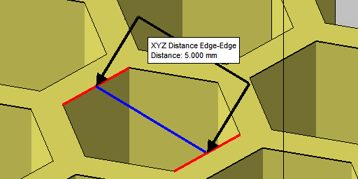
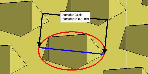
|
Rectangular, Hexagonal, Circular, Column only |
| Pattern wall thickness |
Thickness of walls between holes, or gap between columns |
|
| Perimeter wall thickness |
Generates a wall along the perimeter of this thickness |
|
| Polygon corner |
Affects triangle resolution of the circular features |
Circular, Column only |
| Minimum pattern area |
A filter to help suppress fragments. Holes are suppressed (filled) if area cannot meet minimum fraction |
|
| Minimum structure hatch |
A filter to suppress any polygon stretches shorter along the XY plane than the given value. |
|