
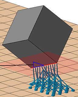
Builds a scaffolding under and around the part and supports it with bars
This is an area-supporting action. It fills the volume underneath supportable surface areas subdivides the determined support into unit cells which are then filled with lattice topology. From the scaffolding thus created, individual bars support the respective downskin clusters. If possible, and enabled, whole groups of eight cells (2×2×2) are collapsed into single cells.
Jump to:
Main parameters
| Parameter | Description | Notes |
|---|---|---|
| Description |
Holds a text label for the action that remains visible even when the action parameters are collapsed in the script tab |
|
 Color
Color
|
Sets a display color for the support elements generated by this action |
Cannot be reverted once changed, only explicitly set to a new color |
| Cluster |
Search parameters for areas of contiguous triangles requiring supports |
|
| Anchors |
See Anchors section below |
See Anchors |
| Cell width, Cell height |
Sets the size of the smallest cell, and indirectly the angle of diagonal support bars. The ratio of width to height should be kept above a certain value so as to keep the diagonal bars printable. |
|
| Adaptive steps |
The rule of collapsing multiple fully intact lattice cells into the next larger cell size is applied up to this many times. Note that this is only the permissible maximum. If there aren't enough intact cells in a contiguous 2×2×2 arrangement, no collapsing is performed. |
 Comparison of adaptation. Three adaptive steps lighten the lattice considerably more than just one step. |
| Distance part to lattice |
This minimum distance is enforced between lattice and part surface when hugging the surface contours with the lattice scaffolding. |
|
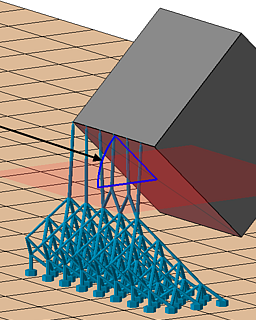
| Lattice go around the part |
If enabled, an additional layer of lattice cells beyond the part circumference is generated to fill even more volume with rigid support but consequently consumes significantly more build space on the platform. This helps with supporting part sections otherwise too far up, or significantly undercut by part structures further down. |
|
| Gap between part and lattice |
Artificially increases the gap between lattice grid and part surface to prevent intersection even on intricate side walls |
|
| Latticing behavior |
Controls the expansion and use of additional lattice cells beyond the originally determined volume.
|
|
| Allow lattice on upskin and sidewalls |
Permit lattice generation in open or closed cavities where it could not normally grow into and where only regular bars would be generated. |
|
|
Baseplate for group
|
Enables or disables group-local baseplate generation |
|
|
Bars per group
|
Puts at most this many bars into a group. A group of bars may have a local baseplate. |
Unavailable when Baseplate for group is set to No |
| Support properties Bar |
Parametrization for the shape of the bars generated by this support action |
|
|
Support properties Baseplate
|
Parametrization for the shape of local baseplates generated for grouped bars |
Anchors
| Parameter | Description | Notes |
|---|---|---|
| Anchor distance |
Defines the space between two anchor points or bars on the cluster surface. This is independent from the lattice cell size. |
|
| Rasterize area, Anchor alignment |
Switches between rectangular, hexagonal, or no anchor placement on the cluster surface. This is independent from the lattice cell topology which always has a quadratic cross section. |
|
| Contour offset to wall |
Anchors keep a distance from a cluster contour that borders a wall (a concave border). |
|
| Free contour offset |
Anchors keep a distance from a cluster contour that does not border a wall. |
|
| Down-oriented points |
Puts a dedicated bar at a cluster's lowest point |
|
| Corners |
Puts dedicated bars into corners of a cluster's contour |
|
| Add bars to medial axis |
Traces the centerline of narrow cluster passages to ensure good support in places where neither the regular, area-filling pattern, nor the contour-tracing pattern would fit. |
|
| Medial axis contour offset |
Narrow passages may be at most twice this wide to still receive the medial axis supports. |
|
| Borders |
Traces the cluster contours with supports |
|
| Z-range limitation, Minimal z value, Maximal z value |
Places anchors only within this range even when the associated clusters span greater ranges |
|
| Single down point tips |
Puts a dedicated bar on downward-facing protrusions whose sides would otherwise not qualify for cluster detection. This is off by default. |
|
| Sharp edges |
Toggle to support down-facing edges with a line of additional bar supports each |
|
| Maximum edge angle to XY plane |
Specify a threshold angle from the horizontal for the sides of an edge from which it becomes eligible to receive support |
|
| Neighbor area angle |
Specify a "critical angle" for the surface that itself is not critical but terminates in the sharp edge. |
|
Support properties Baseplate
These local baseplates generate for groups of bars when is set to Yes. These baseplates are distinct from .
| Parameter | Explanation | Notes |
|---|---|---|
| Outer offset |
Distance by which the minimum contour formed by the contact points of a group's bars is extended to make the base plate's contour. This is the minimum distance before tapering. For the Pattern of Point connection net, no offset is generated. Instead this value is used to derive the wall thickness of the point connections, using effectively twice this value. |
|
| Maximum height |
The base plate's thickness |
|
| Taper angle |
Applies a taper to the base plate's circumference. Positive angles taper the plate towards the top. Tapering only ever adds onto the contour offset. |
|
| Pattern |
A selection of structures applicable to the baseplate |
|
| Cell size |
Size of the holes for Rectangular and Hexagonal, measured at right angles between wall surfaces, or outer diameter for Circular and Column, respectively 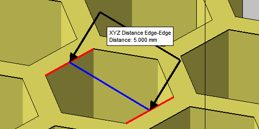 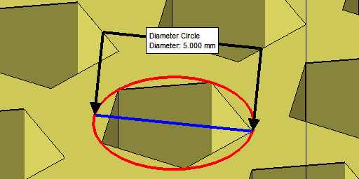
|
Rectangular, Hexagonal, Circular, Column only |
| Pattern wall thickness |
Thickness of walls between holes, or gap between columns |
|
| Perimeter wall thickness |
Generates a wall along the perimeter of this thickness |
|
| Polygon corner |
Affects triangle resolution of the circular features |
Circular, Column only |
| Minimum pattern area |
A filter to help suppress fragments. Holes are suppressed (filled) if area cannot meet minimum fraction |
|
| Minimum structure hatch |
A filter to suppress any polygon stretches shorter along the XY plane than the given value. |
|