
Traces an edge with a polyline. Use when the edge's side walls do not qualify as area clusters for volume support.
 Previously called
Edge with polyline
Previously called
Edge with polyline
Definition of "edge" in the context of this support action
- non-flat junction between two triangles
- convex on the outside (diverging normal vectors)
- angle between adjacent normals of 40° and more
- visible in orthogonal -Z projection, ignoring self-occlusion
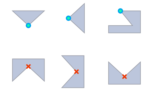
Part sections seen from the side. The top row shows edges supportable with this action, the bottom row shows edges ignored by it. Not shown: Angle minimum of 40° between normals of triangles along a qualifying edge.
| Parameter | Description | Notes |
|---|---|---|
| Minimum, Maximum edge length |
Edges beyond the range of lengths specified here are disregarded for applying supports. |
|
| Maximum polyline curvature |
Sets the curvature that a polyline may have at most. If this maximum value is exceeded, a new polyline begins. |
0-180° |
| Maximum edge angle to XY-plane |
Describes the maximum angle between an edge and the XY plane. If the maximum angle is exceeded, the edge is disregarded for applying supports. |
0-90° |
|
Create anchor on curvature |
Affects on which curvature of the edge a new anchor point is added. The anchor points are created around the edge. |
0-180° |
| Neighbor area angle |
Angle of triangles against the horizontal, along an edge, where (in Z) one of the triangles is below the edge. Edges where the lower triangle is angled against the horizontal shallower than this angle do receive edge support, too. |
0-90° |
| Anchor distance |
Sets the distance between two anchor points |
1-100 mm |
| Contour offset |
Sets the distance between an anchor point and a clear area |
0-5 mm |
| Startpoint distance |
Sets the border distance between the edge and the start of the support structure |
0-5 mm |
| Reinforcement lines per side |
Adds additional polyline supports parallel to edges for reinforcement. Note: These are generated in pairs, one on either side of the original polyline. When used on a peripheral edge, the outer reinforcement may not connect to anything. If the reinforcement distance is chosen too large with respect to the melt pool distance, these polylines may just waste exposure time without actual benefit.
|
0-5 |
| Reinforcements distance |
The additional parallel polyline supports are placed this far apart. |
|
| Support properties |
See Polyline supports reference |