
 Unify Surface Orientation
Forces sets of adjacent surfaces to have consistent orientations all facing the same way. This helps to ensure that lighting is correct in renderings, and is also useful when modeling, and offsetting surfaces.
This tool modifies the orientation of surfaces based on topology. It is useful to fix surface orientation on smaller parts (for example, a door handle) where it might be difficult to move the camera around in order to see all the surfaces at the same time.
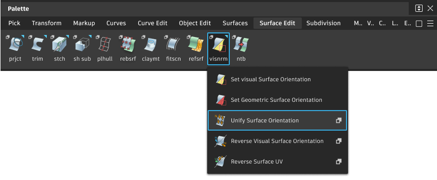
Access this tool from the Surface Edit tool palette:
Unify Normals Control options
Unify Type
Visual – Unify the visual normals. Construction history is preserved.
Visual and Geometric – Unify geometric normals, then reset visual normals to match geometric normals on all selected surfaces.
Geometric – Unify geometric normals only. Visual normals on changed surfaces retain their direction. You are prompted to remove history when you Unify. This option is available only when the Geometric Normal Flips option is set to Keep Visual Normal in Preferences > General Preferences > Miscellaneous.
Operation
- Reverse U, V – Reverses the direction of the U or V isoparametric curves, respectively.
- Swap UV – Swaps the isoparametric curves so that the U direction becomes the V direction and vice versa.
Unify Surface Orientation workflow
You can modify a collection of patches so that sets of adjacent surfaces face in the same direction. This helps to ensure that lighting is correct in renderings, and is also useful when modeling, and offsetting surfaces.
To unify the surface orientation
Double-click the Unify Surface Orientation tool icon.
The Unify Normals Control window opens.
To unify the visual orientation, select Visual as the Unify Type and proceed.
To unify the UV orientation, select Geometric and select the operation.
Reverse U, V – Reverses the direction of the U or V isoparametric curves, respectively.
Swap UV – Swaps the isoparametric curves so that the U direction becomes the V direction and vice versa.
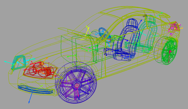
Pick all the surfaces to be unified, and then click the Classify button in the lower right corner of the active window.
Based on the Topology Distance tolerance value (set in Preferences > Construction Options, under the Tolerances > Topology), the surfaces are grouped into sets of adjacent patches. Each set consists of those surface patches that are within the Topology Distance tolerance. The sets are drawn in different colors to help differentiate them.
An arrow shows the direction of the unified surface orientation on each set. To change the orientation of the set, click on the arrow.
When all surfaces are oriented correctly, click Unify.
You can continue changing surface orientations, then clicking Unify again, until you select another tool.
If you selected Visual, construction history is preserved during this operation.
If you selected Geometric, you are prompted to remove history.