
General Information dialog
Use the General Information dialog to specify information for a part program and the type of circular interpolation your CNC uses.
General Information dialog - Mill
The General Information dialog enables you to specify information for a part program such as machining data, subprograms support for milling and drilling operations (if your CNC is capable) and the type of circular interpolation your CNC uses.
To display this dialog, select Configure Mill > General Information from the menu bar.
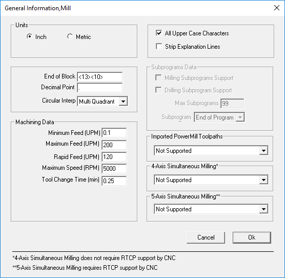
- Units — Select the units.
- End of Block — Specify the end of block character sequence.
- Decimal Point — Specify the character to be used for decimal points. (For U.S. machines, a period is normally used; for European machines, a comma is often used.)
- Circular Interpolation — Select the type of circular interpolation used by your CNC. You can choose Multi Quadrant or Single Quadrant.
Machining Data
Minimum Feed (UPM) — Specify the minimum feed rate value to be used by your CNC.
Maximum Feed (UPM) — Specify the maximum feed rate value to be used by your CNC.
Rapid Feed (UPM) — Specify the rapid feed rate value to be used by your CNC.
Maximum Speed (RPM) — Specify the maximum spindle speed to be used by your CNC.
Tool Change Time (min) — Specify the tool change time to be used by your CNC.
Note: Machining data can be viewed in the Defaults dialog in PartMaker.All Upper Case Characters — Select this option to convert all notes to upper-case characters.
Strip Explanation Lines — Select this option to prevent explanation lines from being written to the NC program file. Explanation lines help improve configuration file documentation. Each explanation line must begin with a semicolon as shown in the following example:
;TOOL CHANGE ON THE NEXT LINE<eob> This is an explanation line. It starts with a semicolon.
T<tool-num><tool-offset>M06<eob>
Subprograms Data
These options are applicable only to PartMaker/Mill:
- Milling Subprograms Support — Select this option if you are using subprograms in a part program and your CNC supports milling subprograms.
- Drilling Subprograms Support — Select this option if you are using subprograms in a part program and your CNC supports drilling subprograms.
- Max Subprograms — Specify the maximum number of subprograms that can be used in a part program.
Subprogram Type
Specify the type of subprogram to be used in a part program:
- Start of Program — Select to place subprogram definitions at the beginning of the part program file.
- End of Program — Select to place subprogram definitions at the end of the part program file. We recommend you use the File End program format at the end of these subprogram definitions.
- Not Available — Select to specify that subprograms will not be output for this part program.
- Individual Files — Select to specify that each subprogram definition will be placed in an individual file. The name of each file consists of the name you specified in ConfigPost and the subprogram number assigned by the system. For example, FANUC03 for Subprogram 03 FANUC is the main part program name and the number 03 is the (internal) subprogram name. The subprogram name is added to the main part program name as the disk file name.
- Separate File — Select to specify that all subprograms will be placed in one file. The name of the subprogram file consists of the output name you specify in ConfigPost (MA represents the subprogram specification) and a file extension of .TXT. For example, the FANUCMA.TXT subprogram file and FANUC.TXT main part program file would be output.
Entering Control Characters
ConfigPost sometimes allows or requires the use of one or more ASCII control characters (non-printable characters). You can embed these control characters in a program format by entering the decimal equivalent of the ASCII code delimited by angular brackets (<>). For example, <13> denotes the ASCII equivalent of a carriage return.
Imported PowerMill Toolpaths
Use this option to specify whether the post processor supports toolpaths that have been imported into PartMaker from PowerMill. This option is available only when using PartMaker/SwissCAM, PartMaker/Turn-Mill, or PartMaker/Mill.
You can select:
- Supported — Select this option if the post processor supports the post processing of toolpaths imported from PowerMill.
- Unsupported — Select this option if the post processor does not support the post-processing of toolpaths imported from PowerMill.
If a PartMaker job file attempts to post process a toolpath imported from PowerMill when Unsupported is selected, PartMaker is unable to post process the toolpath and displays an error message.
Note: As well as selecting **Supported**, the correct formatting must also be configured to post process toolpaths imported from PowerMill, see Configuring a post processor to support imported [PowerMill toolpaths](../configpost-turn-mill-swisscam/configure-postprocessor.md) for more details.4-Axis Simultaneous Milling
Use this option to specify whether the post processor supports 4-Axis Simultaneous toolpaths. This option is available when using PartMaker/SwissCAM, PartMaker/Turn-Mill and PartMaker/Mill.
You can select:
- Supported — Select this option if the post processor supports 4-Axis Simultaneous toolpaths.
- Not Supported — Select this option if the post processor does not support 4-Axis Simultaneous toolpath.
5-Axis Simultaneous Milling
Use this option to specify whether the post processor supports 5-Axis Simultaneous toolpaths. This option is available when using PartMaker/SwissCAM, PartMaker/Turn-Mill and PartMaker/Mill.
Note: To use 5-axis simultaneous toolpaths, your CNC machine must support Rotation Tool Center Point (RTCP).You can select:
- Not Supported — Select this option if the post processor does not support 5-Axis Simultaneous toolpaths.
- (X,Y, Z) in Rotated Coordinate System — Select this option if the post processor supports 5-Axis Simultaneous toolpaths and outputs the X,Y coordinates in a coordinate system that rotates about the Z-axis with the stock.
- (X,Y,Z) in Machine Coordinate System — Select this option if the post processor supports 5-Axis Simultaneous toolpaths and outputs the X,Y coordinates in the Machine Coordinate system, which does not change with stock rotation.
If a PartMaker job file attempts to post process a 5-axis toolpath when Unsupported is selected, PartMaker is unable to post process the toolpath and displays an error message.
General Information dialog - Turn
The General Information dialog enables you to specify information for a part program such as machining data, subprograms support for milling and drilling operations (if your CNC is capable) and the type of circular interpolation your CNC uses.
To display this dialog, select Configure Turn > General Information from the menu bar.
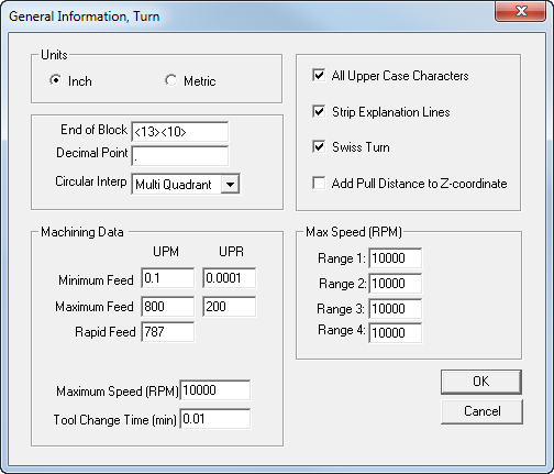
- Units — Select the units.
- End of Block — Specify the end of block character sequence.
- Decimal Point — Specify the character to be used for decimal points. (For U.S. machines, a period is normally used; for European machines, a comma is often used.)
- Circular Interpolation — Select the type of circular interpolation used by your CNC. You can choose Multi Quadrant or Single Quadrant.
Machining Data
Minimum Feed — Enter the minimum programmable feed rate in UPM and UPR.
Maximum Feed — Enter the maximum programmable feed rate in UPM and UPR.
Maximum Speed — Enter the maximum programmable spindle speed.
Rapid Feed — Enter the maximum rapid traverse rate.
Tool Change Time (min) — Enter the tool change time (in minutes) to be used by your CNC.
Note: Machining data can also be viewed in the Defaults dialog in PartMaker.All Upper Case Characters — Select this option to convert all notes to upper-case characters.
Strip Explanation Lines — Select this option to prevent explanation lines from being written to the NC program file. Explanation lines help improve configuration file documentation. Each explanation line must begin with a semicolon as shown in the following example:
;TOOL CHANGE ON THE NEXT LINE<eob>
T<tool-num><tool-offset>M06<eob>- Swiss Turn — Select this option if you are specifying information for Swiss-type machines. Checking this box indicates to PartMaker to begin reading a post configuration file in the Collet Re-Chuck,Turn section located under Other Formats.
- Add Pull Distance to Z-coordinate — When using Material Control Process “Pull with Sub-Spindle”, selecting this option updates all Z-related words (
<z-coord>,<depth-abs>, etc.) for all consecutive processes on the main spindle by adding the “Pull Distance(Zp)”. - Max. Speed (RPM) — Range 1-4. These options represent the maximum attainable spindle speeds in each of the lathe's gear ranges. If a range is not available, set the value to zero.
- Entering Control Characters — ConfigPost sometimes allows - or requires - the use of one or more ASCII control characters (non-printable characters). You can embed these control characters in a program format by entering the decimal equivalent of the ASCII code delimited by angular brackets (<>). For example, <13> denotes the ASCII equivalent of a carriage return.
General Information dialog - WireEDM
The General Information dialog enables you to specify information for a part program, such as machining data and the type of circular interpolation your CNC uses.
To display this dialog, select Configure EDM > General Information from the menu bar.
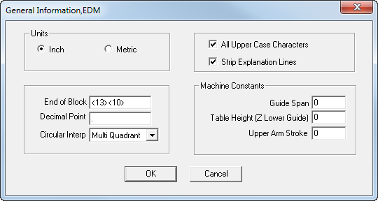
- Units — Select the units.
- End of Block — Enter the end of block character sequence.
- Decimal Point — Enter the character to be used for decimal points. (For U.S. machines, a period is normally used; for European machines, a comma is often used).
- Circular Interpolation — Select the type of circular interpolation used by your CNC. You can choose Multi Quadrant or Single Quadrant.
Machining Constants
- Guide Span — Enter the (Z) distance measured between the upper and lower guides.
- Table Height (Z Lower Guide) — Enter the distance from the work table down to the lower guide.
- Upper Arm Stoke — Enter the maximum travel distance of upper guide.
- All Upper Case Characters — Select this option to convert all notes to upper-case characters.
- Strip Explanation Lines — Select this option to prevent explanation lines from being written to the NC program file.
Explanation lines help improve configuration file documentation. Each explanation line must begin with a semicolon as shown in the following example:
;TOOL CHANGE ON THE NEXT LINE<eob> This is an explanation line. It starts with a semicolon.
T<tool-num><tool-offset>M06<eob>- Entering Control Characters — ConfigPost sometimes allows or requires the use of one or more ASCII control characters (non-printable characters). You can embed these control characters in a program format by entering the decimal equivalent of the ASCII code delimited by angular brackets (<>). For example, <13> denotes the ASCII equivalent of a carriage return.