Regulator events are used to provide direct and indirect control of regulator structures e.g. weir crest levels, pump switching, pump speed etc.
In InfoWorks networks, regulator events can be used instead of Real Time Control (RTC), or to override RTC when directly controlling a regulator.
The events can also be used to provide output values for an RTC table when indirectly controlling a regulator.
Using Regulator Events instead of, or in conjunction with RTC can help in avoiding the creation of a large number of Scenarios or a large number of branched networks when editing controls.
To use a regulator event in a simulation, select the event in the Schedule Hydraulic Run View or SWMM Schedule Hydraulic Run View when scheduling a run.
Regulator event data can be viewed and edited on the Event Editor.
Sub-Events and Profiles
Regulator events, like many other types of event, are divided into:
- sub-events - a time period during which input to the system takes place
- profiles - describing the input at a single object (regulator or RTC table)
For more details on how InfoWorks ICM deals with sub-events and profiles, see the main Events topic.
Each column on the Event Editor grid represents a single control profile, and the object at which the profile is applied is shown in the column header.
There are three types of regulator profile:
- Direct: the regulator profile values are used to directly control the regulated variable of an individual regulator. Linear interpolation is used between sub-event timesteps (except for pump state where no interpolation is applied between timesteps).
- DirectStep: the regulator profile values are used to directly control the regulated variable of an individual regulator. No interpolation is applied between sub-event timesteps.
- Indirect: - InfoWorks networks only - the regulator profile provides a time-varying series of measure values of the regulated variable that can be used in RTC tables to indirectly control one or more regulators.
Note that when a direct and indirect profile measure the same variable at the same time, then the direct profile will take priority.
In InfoWorks networks, a special value of -9999 may be used in a profile to indicate that the regulator should use RTC at a time within a sub-event. If the last value in the sub-event is set to -9999, RTC will be used from the end of the sub-event until the start of the next sub-event.
Direct and DirectStep profiles
Direct and DirectStep profiles can be used to model a regulator under manual control.
The values in the profile represent the measured values of the regulated variable and will replace RTC controls for the regulator if RTC is present.
To apply the profile to a regulator in the network, select Profile type of Direct of DirectStep and set Reference to the Object ID of the regulator in the event Profile Properties Dialog.
Indirect profiles
InfoWorks networks only.
Indirect profiles provide indirect control by providing a time series of measured values which are used in RTC Tables (of input type Time) to indirectly control one or more regulators.
To apply the profile to a RTC table, select Profile type of Indirect and set Reference to the name of the RTC Table in the event Profile Properties Dialog. The reference should take the form RegulatorID.TableName for tables defined in regulators in the RTC, or TableName for tables defined in the Global section of the RTC.
Example
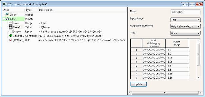
The example below shows the RTC for a sluice gate indirectly controlled by the height above datum at node 120. The required heights for node 120 are specified in Table 'TimeInputs'. A Controller is then used to operate the sluice gate in order to maintain these heights.
A regulator event can be used to replace the output time series in the RTC table 'TimeInputs'.
- Create a regulator event in the tree
- In the profile properties dialog of the event, specify a Profile type of Indirect and reference the table 'TimeInputs' by entering a Reference of TimeInputs.
- Create a new run and drop the regulator event into the Schedule Hydraulic Run View.
- Run the simulation
The time series in the regulator event will replace the time series in the RTC table, at the places where the regulator subevent times overlap the table times.

|
Component |
Parameters |
Effect |
|---|---|---|
|
RANGE 'Time' |
Range type: T - Time Location node: Minimum: Maximum: |
TRUE if height above datum is between - / + infinity |
|
TABLE 'TimeInputs' |
Measurement: Height above datum Input Range: Time Type: Linear Input/Output grid: Time vs Height above datum |
Relationship between range type defined in RANGE 'Time' and Height above datum (at node 120) |
|
RANGE 'Sensor' |
Range type: Height above datum Location Definition: 120 Minimum: 0.0 mAD Maximum: 1.0 mAD |
TRUE if Height above datum is greater than or equal to 0.0 mAD and less than or equal to 1.0 mAD |
|
CONTROLLER 'Controller' |
Type: PID Measurement: 60 Sensor: Sensor Rule type: OFF |
Measurement interval of 60s Measurement range used to provide input signal to PID controller defined by RANGE 'Sensor' |
|
RULE '_Default_' |
Condition: _Default_Rule type: CTRL Controller: Controller Setpoint type: Variable (TimeInputs) |
Operate sluice gate in order to maintain heights as defined in TABLE 'TimeInputs' |
