
Sustainable Urban Drainage System (SUDS) in InfoWorks networks and Low Density Development (LID) control objects in SWMM networks are specified as part of the Subcatchment data and are used to define the parameters which model the outflow from the SUDS/LIDs structures which are associated with a subcatchment.
In InfoWorks networks, SUDS control objects can also be specified as part of building data and are also used to define the parameters which model the outflow from the SUDS/LID structures which are associated with a building.
A description of each type of SUDS/LID control is outlined below.
Bio-retention cell
Biological retention cells/facilities are landscaped depressions used for the storage and infiltration of storm water through plants, soil and micro-organisms in areas with relatively lower ground level before draining to a drainage bed usually comprised of gravel. A bio-retention cell may optionally contain some form of under-drainage system.
The following diagram illustrates how a bio-retention cell structure is modelled in InfoWorks ICM:
KEY
| Bio-retention Cell* | Description |
|---|---|
| SURFACE LAYER | The ground (or pavement) surface which receives direct rainfall and flow from adjacent areas, stores flow in depression storage and generates runoff that enters the drainage system. |
| SOIL LAYER | An engineered soil mixture which supports vegetative growth. |
| STORAGE LAYER | A bed of crushed rock or gravel which provides storage for the flow. |
| Underdrain | A system which drains water from the storage layer of the bio-retention cell. Note that underdrain systems are optional features in bio-retention cells. |
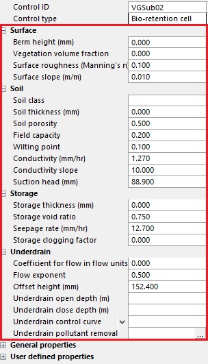
*The individual parameters which define each part of a bio-retention cell are described in the SUDS Control Data Fields and LID Control Data Fields (SWMM).
|
|
| SUDS properties for a bio-retention cell | LID properties for a bio-retention cell |
Rain garden
Rains garden are similar to a bio-retention cells but without a gravel bed (storage layer). They typically have a small shallow depression (about 100 mm to 300 mm deep) which is designed to overflow into a piped drainage system. Beneath this, flow can percolate through to the underlying soil.
The following diagram illustrates how a rain garden is modelled in InfoWorks ICM:
KEY
| Rain Garden* | Description |
|---|---|
| SURFACE LAYER | The ground (or pavement) surface which receives direct rainfall and flow from adjacent areas, stored flow in depression storage and generates runoff that enters the drainage system. |
| SOIL LAYER | Engineered soil mixture which supports vegetative growth. |
*The individual parameters which describe each part of a rain garden are described in the SUDS Control Data Fields and LID Control Data Fields (SWMM).
Green roof
Green roofs are essentially a vegetated surface which provide retention and attenuation of flow and encourage evapotranspiration. A drainage mat allows excess percolated flow to drain off the roof. Outflow (down-pipes)from a green roof are rarely designed to be a constraint.
The following diagram illustrates how a green roof is modelled in InfoWorks ICM:
KEY
| Green Roof* | Description |
|---|---|
| SURFACE LAYER | The ground (or pavement) surface which receives direct rainfall and flow from adjacent areas, stored flow in depression storage and generates runoff that enters the drainage system. |
| SOIL LAYER | Engineered soil mixture which supports vegetative growth. |
| DRAINAGE MAT | A mat of plate that lies beneath the soil and above the roof structure. The drainage mat conveys any water that drains through the soil layer off the roof. |
*The individual parameters which define each part of a green roof are described in the SUDS Control Data Fields and LID Control Data Fields (SWMM).
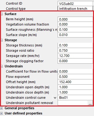
Infiltration trench
These are linear excavations filled with stone aggregate or other void-forming material used to capture runoff from upstream impermeable areas and encourage infiltration for underground water recharge.
The following diagram illustrates how an infiltration trench is modelled in InfoWorks ICM:
KEY
| Infiltration Trench* | Description |
|---|---|
| SURFACE LAYER | The ground (or pavement) surface which receives direct rainfall and flow from adjacent areas, stored flow in depression storage and generates runoff that enters the drainage system. |
| STORAGE LAYER | Bed of crushed rock or gravel which provides storage for the flow. |
| Underdrain | A system which drains water from the storage layer of the infiltration trench. Note that underdrain systems are optional features in infiltration trenches. |
*The individual parameters which define each part of an infiltration trench are described in the SUDS Control Data Fields and LID Control Data Fields (SWMM).
|
|
| SUDS properties for an infiltration trench | LID properties for an infiltration trench |
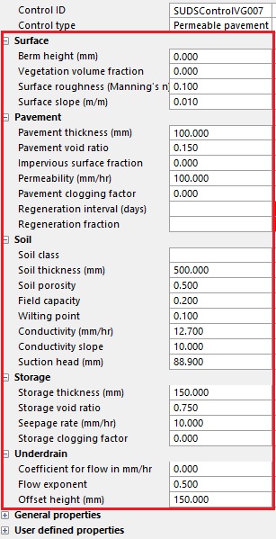
Permeable pavement
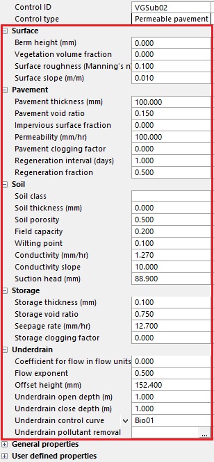
Permeable pavements are block paving or permeable asphalt on top, high voids geo-grid in the middle or stone media, and the base can be lined or soil. A large majority of rainfall will pass through the pavement into a storage layer below where it can infiltrate into the soil below. A layer of soil may optionally be included between the permeable pavement and the storage layer. The outlet is usually a form of hydraulic control.
The following diagram illustrates how a permeable pavement is modelled in InfoWorks ICM:
KEY
| Permeable Pavements* | Description |
|---|---|
| SURFACE LAYER | The ground surface which receives direct rainfall and flow from adjacent areas, stored flow in depression storage, and generates runoff that enters the drainage system. |
| PAVEMENT LAYER | A layer of porous concrete or asphalt. |
| SOIL LAYER | Engineered soil mixture which supports vegetative growth. Note that this layer is optional for permeable pavements. |
| STORAGE LAYER | The high voids geo-grid. |
| Underdrain | A system, normally a hydraulic control, which drains water from the storage layer of storage layer. Note that underdrain systems are optional features in permeable pavements. |
*The individual parameters which define each part of a permeable pavement are described in the SUDS Control Data Fields and LID Control Data Fields (SWMM).
|
|
| SUDS properties for a permeable pavement | LID properties for a permeable pavement |
Rain barrel
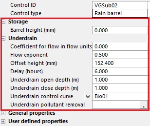
Rain barrels are an enclosed overground or underground stormwater collection facilities that collect roof runoff during storm events. They can either slowly release flow into the system or allow the re-use of rainwater during dry weather periods.
The following diagram illustrates how a rain barrel is modelled in InfoWorks ICM:
KEY
| Rain Barrel* | Description |
|---|---|
| STORAGE LAYER | A container or tank which provides storage for the flow. |
| Underdrain | A system which drains water from the rain barrel. |
*The individual parameters which define each part of a rain barrel are described in the SUDS Control Data Fields and LID Control Data Fields (SWMM).
|
|
| SUDS properties for a rain barrel | LID properties for a rain barrel |
Rooftop disconnection
Rooftop disconnection is when roof drain pipes drain to pervious areas and lawns instead of directly into the drainage system. In some cases, the roof drain pipes can drain to a permeable pavement.
The following diagram illustrates how a rooftop disconnection is modelled in InfoWorks ICM:
KEY
| Rooftop Disconnection* | Description |
|---|---|
| SURFACE LAYER | The ground (or pavement) surface which receives direct rainfall and flow from adjacent areas, stored flow in depression storage and generates runoff that enters the drainage system. |
| Underdrain | The drainage from the surface layer. |
*The individual parameters which define each part of a rooftop disconnection are described in the SUDS Control Data Fields and LID Control Data Fields (SWMM).
Vegetative swale
There are many variations in the design of swales. In general terms a swale is a vegetation covered overground channel, of any depth between 500mm to 2m or more. It can collect, transport and convey stormwater. Conveyance within the swale is usually restricted and allows more time for water to infiltrate into the soil below. It can be used as connection with other urban drainage facilities. When it is full, it will spill from the surface at the bottom end and cause overland flow.
The following diagram illustrates how swale is modelled in InfoWorks ICM:
KEY
| Vegetative Swale* | Description |
|---|---|
| SURFACE LAYER | The ground (or pavement) surface which receives direct rainfall and flow from adjacent areas, stored flow in depression storage and generates runoff that enters the drainage system. |
*The individual parameters which define each part of a vegetative swale are described in the SUDS Control Data Fields and LID Control Data Fields (SWMM).
The SWMM Reference Manual, Volume III, Water Quality contains further information about types of LID controls.