
Manufacturing Configuration Dialog Box Reference
Click Configuration on the the TruPlan ribbon, or double-click a manufacturing configuration in the TruPlan browser.
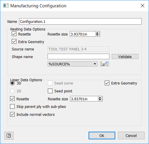
If necessary, enter a name for the configuration in the Name box.
Nesting Data Options
Rosette
Select to include rosette geometry in output.
Rosette Size
Set a value appropriate for your model; for example, a rosette size of 10mm will be too difficult to see compared to a large object like a wing.
Extra Geometry
Select to include extra geometry in the nest.
Source Name
The root node of the part; a read-only field.
Shape Name
By default this contains the same 3D text you entered into the Extra Geometry dialog box. Use this box and its related controls (Validate, variables) as you would in the Extra Geometry dialog box.
Laser Data Options
3D
3D ply geometry; this is a toggle switch with 2D. In most cases you want your output to be 3D.
2D
2D flattened geometry. This is a toggle switch with 3D. This is only available if flatten geometry exists within the part, and is sometimes used to make sure the ply shapes are correct. You might also use this to lay several plies on top of one another to be cut all at once. 2D shapes are projected at their location in the model.
Seed Curve
The seed curve that was defined in the strategy. This is only available if a seed curve exists in the part.
Seed Point
The seed point that was defined in the strategy; it defines where you first place the material before spreading it out. This is only available if a seed point exists in the model and if Rosette is selected. If Seed Point and Rosette are both selected, the rosette will be moved to the location of the seed point.
Extra Geometry
Include any extra geometry you created for the part.
Rosette
Include a rosette for each ply in the output file. A rosette shows the direction of a ply at the rosette origin. The long end of L shape indicates the grain direction for each ply.
Rosette Size
Like with nesting data, set a value appropriate for your model; use larger rosettes for large parts.
Skip Parent Ply With Sub-Plies
Sub-plies are contained within the parent ply; use this option to exclude the parent ply and only include the sub-plies in the output. You might do this if you are only laying the sub-plies and do not need to see a projection of the entire ply. Conversely, you might want to actually include the parent before projecting the sub-plies so that the operator can see what the entire ply is supposed to look like.
Include Normal Vectors
Select whether to include normal vectors when creating 3D laser output. Normal vectors are calculated based on the reference surface and are crucial to getting correct laser projection. Autodesk recommends leaving this selected.