The Cutting Tool Manager
To maximize the accuracy of the verification process, you can create and manage tool models that accurately represent the physical tooling you use in your shop.
To access the Cutting Tool Manager, click Tools on the Manage tab:

This accesses the Tools page of the Resource Manager. Alternatively, you can access the Resource Mananger using the Resources button at the bottom of the Project Navigator view:

The Resource Manager > Tools page lets you view and manage your custom cutting tools:
 Note: After initial installation of Autodesk CAMplete TruePath, there should be no tools in the database.
Cutting Tool Model Design
In Autodesk CAMplete TruePath, tools are organized in a tree type hierarchy:
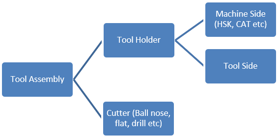
Creating and Editing A New Tool Assembly
This example will show how to create a completely new tool assembly that uses an HSK tapered tool holder and a 50 mm diameter bullnose tool with a 5 mm corner radius.
To create a new Tool Assembly
Click Create to display the Create Tool Components dialog.
This dialog allows you to create a new tool assembly and all of the required sub components.
Enter the names for the Tool Assembly, Tool Holder, Machine Side, Tool Side and Cutter.
Note: The names of the components must all be unique. Names cannot be shared or repeated inside of the tool database.For this example, use the following names:
Tool Assembly:
Demo 50 mm Bullnose
Tool Holder:
Demo HSK Holder
Machine Side:
Demo HSK Machine Side
Tool Side:
Demo Tool Side
Cutter:
Demo 50 mm Bullnose Cutter
For the Machine Side Type, set it to create an HSK Adapter.
For the Tool Side Type, set it to create a Tapered Endmill Adapter.
For the Cutter Type, set it to create a Corner Rounded End Mill:
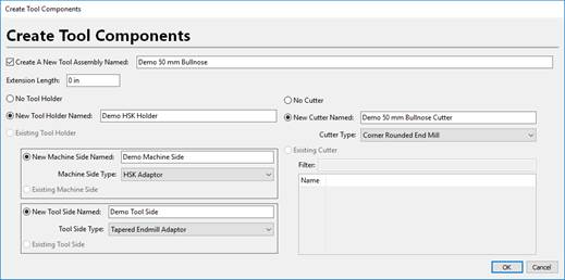
When the data is entered correctly click OK to create the new components.
The new Tool Assembly will appear in the grid.
At the moment, no geometric parameters have been specified, so the preview view will not show anything.
You can now filter the objects by their type using the drop list:
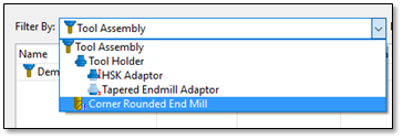
This will choose whether the grid is displaying Tool Assemblies, Tool Holders, Machine Sides, Tool Sides and Cutters.
To edit the Machine Side Adaptor:
Switch the filter to HSK Adaptor.
Only HSK machine sides will now be displayed in the list.
Select the Demo HSK Machine Side that was just created:
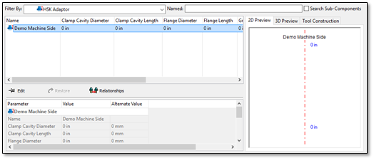
The parameters for this component appear in the lower grid.
A 2D Preview of the tool is displayed on the right. This can also be switched to a 3D Preview of the tool item or the Tool Construction, which describes which components of the tool are defined.
Click Edit to begin editing the parameters.
You can edit each value in either mm or inches using the Value and Alternate Value columns. As changes are made, the 2D and 3D Previews are updated dynamically.
Note: Right clicking on the 2D Preview allows you to control the dimension labels. Available options are:Labels Off – No dimension labels will be shown.
Light Labels – Only the most important labels are shown.
Full Labels – All labels will be displayed.
You can also use the arrow keys to move around in the grid and press Enter to edit a value and Enter when the value editing is completed. As you select each parameter in the grid, the associated label in the 2D Preview will be highlighted (if it’s currently visible in the grid depending on the label output mode).
For this example, use the following values:
Values:
Preview:
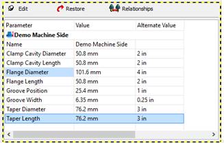
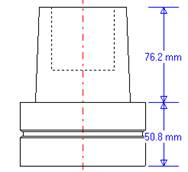
When the correct values are entered, click Edit again to commit the changes to the tool database.
Note: You can also see the 3D Preview of the tool by switching to the 3D Preview tab.
To Edit the Tool Side Adapter
Switch the filter to Tapered Endmill Adapter and select the Demo Tool Side component that was created earlier.
Click Edit.
For this demo, enter the following dimensions:
Values:
Preview:
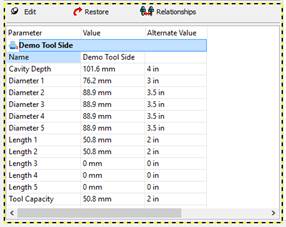
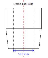
Click Edit again to commit the changes to the tool database.
Switch the filter to Tool Holder and select the Demo HSK Holder.
You will see all of the parameters for the Machine Side and the Tool Side appearing together in the lower grid. By clicking Edit you can edit both of them at the same time if needed.
To Edit the Cutter
Switch the filter again to Corner Rounded End Mill and select the Demo 50 mm Bullnose Cutter that was created.
Click Edit.
For this demo, enter the following dimensions:
Values:
Preview:
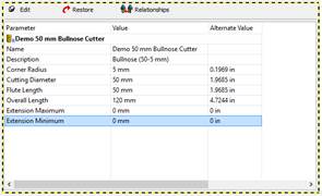
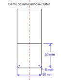
Click Edit again to commit these changes to the tool database.
To Edit the Tool Assembly
Switch the filter back to Tool Assembly and re-select the Demo 50 mm Bullnose (5 mm rad) tool assembly. The entire tool assembly parameters will appear in the lower grid. Again, these can all be directly edited from here.
Notice that the cutting tool is inside of the holder because no gauge length has been entered.
Click Edit.
For the Extension Length, enter 75 mm. This is the distance from the bottom of the tool holder to the bottom of the tool (ie. the “stick-out” distance).
The entire tool assembly should now look correct in the 2D Preview:
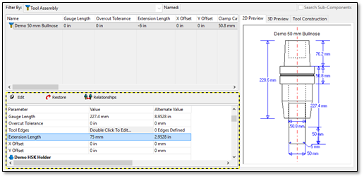
Click Edit again to commit this change to the database. The new tool assembly is now ready for use in a project.
To Select a Tool Assembly in a Project
Close the Resource Manager if it is open.
With your project loaded, open the CAM Wizard.
Go to the Cutting Tool page.
Select the tool that you want to change.
In the Click to Change column click Change.
The Select Tool Assembly dialog will be displayed.
This dialog shows the available tool assemblies on the left, a preview of the new selection in the middle, and a preview of the current selection on the right.
Select the new Demo 50 mm Bullnose (5 mm rad) in the grid:
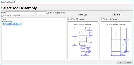
Click OK.
The new tool will now replace the original one and will be used in the simulation.
