The Display Wizard controls how different parts of the project are displayed.
To access the Display Wizard, click Wizard on the Simulation View tab of the ribbon:

Alternatively, you can access the Display Wizard through button on the Project Navigator:

The Display Wizard has pages for each part of the project:
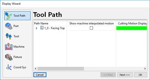
Tool Path – Control the display of the tool paths in the current document.
Part – The part geometry display properties.
Tool – Control the cutting tool display properties for individual tools or all tools.
Machine – Machine display properties
Fixture – The fixture geometry display properties.
Coord Sys – Control the display of coordinate systems in the project.
Display Wizard - Tool Path
The tool path page is used to control how each individual tool path is displayed.
If the program is collapsed in the grid, then the display properties are applied to all of the operation in the program.
Expand the program(s) to individually set the display of each individual operation in the program.
The columns control how the path is displayed in the 3D view:
a. Show Machine Interpolated Motion – Shows all of the machine motion including tool changes, clearance moves that are not normally displayed in the path lines.
b. Cutting Motion Display Color – Sets the color of cutting motions.
c. Rapid Motion Display Color – Sets the color of rapid motions.
d. Draw Rapids as Dashes – Draw rapid moves as dashed lines.
e. Interpolated Motion Color – Set the color of the machine interpolated motion (see above)
f. Advanced – Click to get the Advanced properties of the tool path(s):
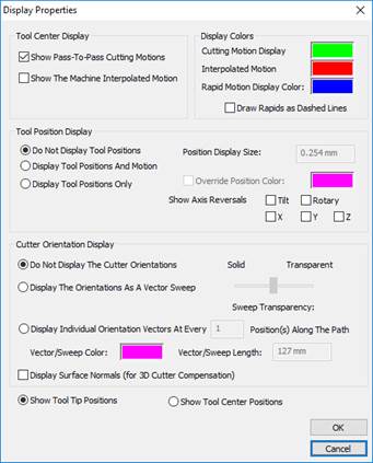
Display Wizard - Part
The part page controls the display of the part geometry.
Each geometric entity is displayed in the grid. By default, if all geometry has the same display properties, the part will be collapsed:
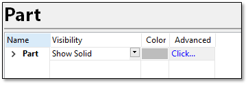
The columns are:
Visibility – Control how the object is displayed. It can be set to Hide, Show Solid, Show Solid With Edges, Show Wireframe, Show Transparent and Show Transparent With Edges.
Color - Double click the Color column to control the color of the part geometry.
Advanced – Adjust the display properties by clicking the Advanced column. The Display Properties will be displayed:
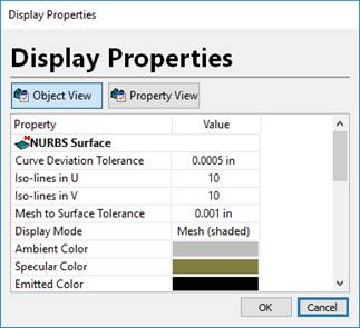
For NURBS surfaces, you can control the various mesh tolerances through this page.
Display Wizard - Tools
The tool page lets you control the display of individual tools or ALL tools in the project.
The Current File mode shows all of the cutting tools in the project:
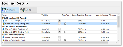
Each tool assembly shows an entry for the Tool Holder and the Cutting Tool. This lets you control the display of each tool assembly independently.
The columns are:
Visibility – Control how the object is displayed. It can be set to Hide, Show Solid, Show Solid With Edges, Show Wireframe, Show Transparent and Show Transparent With Edges.
Draw Top – For cutting tools un-check this option to prevent the top of the tool from being filled in. In that mode, you can look inside the tool to see contact with the design surface.
Curve Deviation Tolerance – The allowable deviation from the surface display mesh relative to the profile of the holder or tool. Setting this to a smaller number will make the tool geometry more refined (but will slow down collision checking).
Mesh to Surface Tolerance – The allowable deviation from the surface display mesh relative to the actual NURBS surface used to represent the tool. Setting this to a smaller number will make the tool geometry more refined (but will slow down collision checking).
Switching to All Files will set the same display properties but will apply them to all tools in the project:

Display Wizard - Machine
The Machine page lets you control the display of the various machine components:
The parts of the machine are broken down by Body Parts, Axes and Visualization Objects:
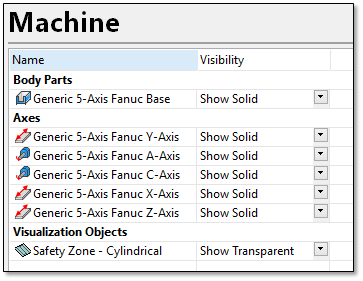
For each object, the Visibility can be set to Hide, Show Solid, Show Solid With Edges, Show Wireframe, Show Transparent and Show Transparent With Edges.
Display Wizard - Fixture
The Fixture page controls the display of the fixture geometry.
Each geometric entity is displayed in the grid. By default, if all geometry has the same display properties, the part will be collapsed:
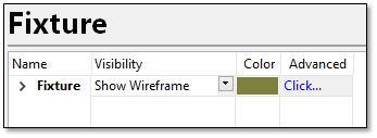
The columns are:
Visibility – Control how the object is displayed. It can be set to Hide, Show Solid, Show Solid With Edges, Show Wireframe, Show Transparent and Show Transparent With Edges.
Color - Double click the Color column to control the color of the part geometry.
Advanced – Adjust the display properties by clicking the Advanced column. The Display Properties will be displayed:
Display Wizard - Coord Sys
The Coord Sys page controls the display of various work datum and coordinate system objects in the project.
Click Coord Sys to show the page.
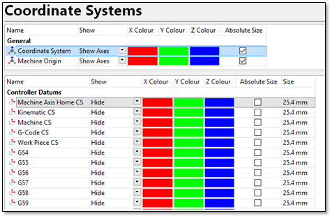
The upper grid shows the Coordinate System objects from the project. These include the job coordinate system and the machine origin.
Show – Hides or shows the coordinate system.
X Color – Set the color of the X-Axis of the coordinate system.
Y Color – Set the color of the Y-Axis of the coordinate system.
Z Color – Set the color of the Z-Axis of the coordinate system.
Absolute Size – Show the coordinate system as an absolute size in the 3D view rather than relative.
The lower grid shows the work datum display objects.
Show – Hide or show the datum. The options are Show Globe (shows the datum as a small spherical globe), Show Axes (shows the datum as XYZ axes) and Hide.
X Color – Set the color of the X-Axis of the coordinate system.
Y Color – Set the color of the Y-Axis of the coordinate system.
Z Color – Set the color of the Z-Axis of the coordinate system.
Absolute Size – Show the coordinate system as an absolute size in the 3D view rather than relative.
Size – Set the absolute or relative size of the datum display object.
Once the visibility options have been adjusted, the Display Wizard can be closed.
