Programs can be managed through the Programs tab on the Ribbon interface:

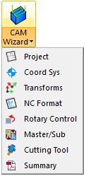
CAM Wizard
The CAM Wizard buttons let you access any of the pages of the CAM Wizard directly:
CAM Files
The Import button is provided here to import more CAM files into the existing project:

Edit
The edit section provides commands to manipulate your programs in the sample project.
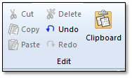
Cut – Cut the currently selected program or operation from the project tree. The object will be placed in the CAMplete Clipboard Object(s).
Copy – Copy the currently selected program or operation in the project tree. The object will be placed in the CAMplete Clipboard Object(s).
Paste – Paste the last copied or cut program or operation into the current location in the project tree.
Delete – Delete the currently selected program or operation from the project.
Undo – Undo the last edit that was made to the project.
Redo – Redo the last undone edit.
Clipboard – Show the CAMplete Clipboard Object(s) view:
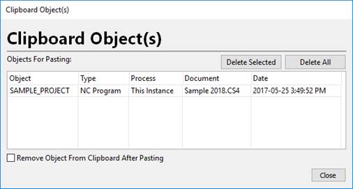
The CAMplete Clipboard Object(s) window shows whatever CAMplete objects were cut or copied from TruePath. This allows you to managed multiple objects and to copy objects from another instance of Autodesk CAMplete TruePath.
a. The grid columns are:
i. Object – Lists the name of the object.
ii. Type – Shows the type of object (NC Program, Machining Operation or CNC Command Lines if you copied lines from the Program Editor)
iii. Process – Which running instance of Autodesk CAMplete TruePath that the object was copied or cut from.
iv. Document – The name of the source document for the object.
v. Date – The date that the object was copied, cut or deleted.
b. Click Deleted Selected to remove the currently selected object(s) in the grid.
c. Click Delete All to remove all objects from the Clipboard.
d. Enable Remove Object From Clipboard After Pasting to automatically delete the object from the clipboard after you have pasted or drag and dropped the object.
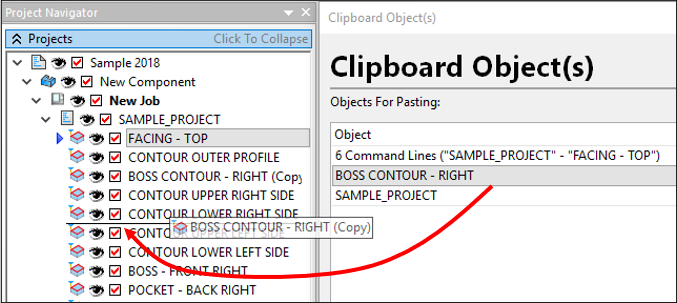
You can drag and drop objects from the Clipboard grid into the Projects tree:
If you click Paste and there is more than one object in the Clipboard, you will need to select it from the grid:
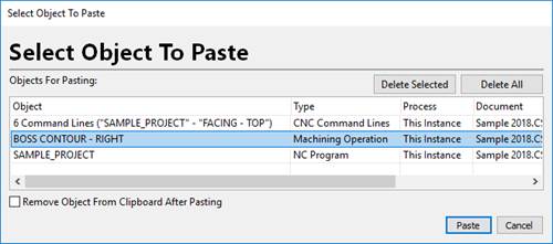
Select the object and click Paste.
If you close Autodesk CAMplete TruePath and there are still objects in the Clipboard, you will be prompted to delete them:
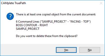
Click Yes to delete them or No to leave them. If you do not delete them, they will be there the next time your run TruePath.
Settings
The Settings buttons are:
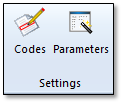
Codes – Shows the Code Navigator view which lets you find command codes in the program. This button is explained in section 15.
Parameters– Show the Parameter Wizard:
Click Parameters in the Ribbon.
The Parameter Wizard will appear:
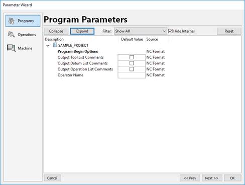
The Parameter Wizard provides access to any custom post processing parameters that belong to your NC Format. There are different parameters that belong to the programs, the operations and the machining setup.
Note: Your NC Format must be setup to use Default Parameters in order for you see any options on this page.The Programs page shows any parameters that might belong to the program.
The parameters appear under each program object. The name of the option appears in the Description column. The Default Value is used to set the value. The Source column shows where the parameters came from. That could be from the NC Format or from the CAM data file. Click Reset to restore any values to the default value.
Click Collapse or Expand to collapse or expand the items in the grid.
Use the Filter drop list to show only entries of the selected type. Once the parameters are being filtered, you can select multiple rows and edit them all at the same time.
Hide Internal will hide any internal parameters that can usually be ignored by the user.
The Operations page shows the same parameters for each operation:
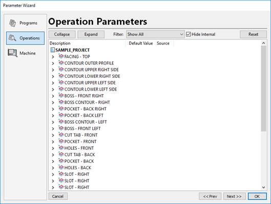
The various columns and buttons are the same for the Programs page and the Operations page.
The Machine page shows the same parameters that belong to the machine.
Tool Paths
The Settings buttons are:

Modify – This allows you to run the Autodesk CAMplete TruePath Modify commands.
In the Projects tree, select the program with the operation(s) that you want to modify.
Click Modify from the ribbon.
Select the Operation(s) (also called Tool Paths) that you wish to modify from the list:
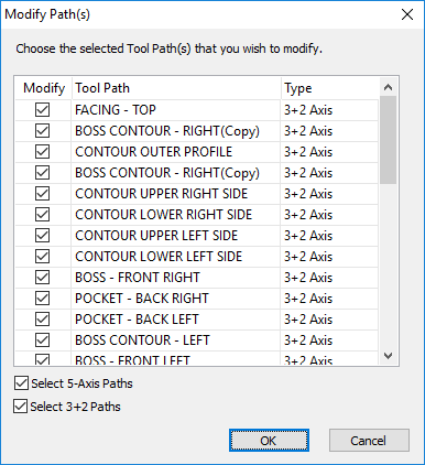
Use Select 5-Axis Paths and Select 3+2 Paths to filter the paths by type.
After selecting the Operations, click OK.
The Modify Path(s) dialog will appear:
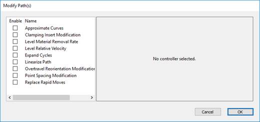
To enable a modification, check it’s option in the right hand grid under the Enable column.
The available options are:
Approximate Curves – This will convert any arcs in the selected operations into point motion.

Enable – Select whether to convert Circular Arcs or Helixes.
Curve Type – The type of arc.
Tolerance – The chordal deviation tolerance to use for the conversion.
Clamping Insert Modification – This will insert automatic rotary and clamping codes into 5-axis tool paths. When the each rotary axis starts moving, the appropriate UNCLAMP code will be inserted before that motion. When each rotary axis stops moving, the appropriate CLAMP code will be inserted after the motion.
WARNING – Consult with CAMplete Solutions BEFORE using this modification.

Clamp A/B/C – Set the M-Code to use to clamp the A, B and C axis. Enter no text to skip that axis.
Unclamp A/B/C – Set the M-Code to use to clamp the A, B and C axis. Enter no text to skip that axis.
Level Material Removal Rate – This option is for backwards compatibility with old CAMplete project files.
WARNING - Please consult with CAMplete Solutions before using this modification.
Level Relative Velocity – This modification will constantly adjust the feedrate of 5-axis tool paths to maintain a constant velocity at the tool tip. This is ONLY for use with machines that do not support any type of tool center point control function such as M128 on Heidenhain, TRAORI on Siemens, G43.4 on Fanuc etc.
WARNING – Consult with CAMplete Solutions BEFORE using this modification. It is provided for backwards compatibility with older machine tools that do not support dynamic machine motion.
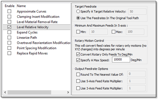
Specify A Target Relative Velocity – This will let you set a target feed at the tool center and ignore the programmed feed in the original operation.
Use The Feedrates In The Original Tool Path – This will use the feed rates in the original tool path as the target.
Minimum And Maximum Feeds In 5-Axis – When the new feed is calculated, this lets you set a minimum and maximum.
Rotary Motion Control – Determines how motions where ONLY the rotaries are moving are handled.
Convert Rotary Only Feed To Deg/Min – Will treat rotary only motions as degrees per minute, which is how most machine controllers operation.
Specify A Max Speed – Sets a maximum speed for rotary only motions.
Round To The Nearest Value Of – Lets you round the new feed rate to a set value.
Use 5-Axis Feed Rate Multiplier – Will multiply the new feed rate by the given factor when the move is 5-axis.
Use 3-Axis Feed Rate Multiplier - Will multiply the new feed rate by the given factor when the move is 3-axis (XYZ motion only).
Expand Cycles – This modification will convert any canned cycles (drilling and pecking) into corresponding G1 and G0 moves. This can be useful for older machines that do not support canned cycles.
WARNING – Consult with CAMplete Solutions BEFORE using this modification. It may not be compatible with your CAM system.
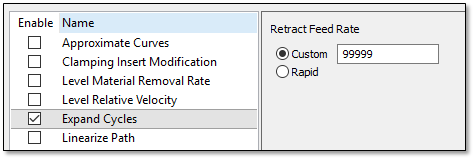
Retract Feed Rate – Use Custom to set a feed rate with a G1 linear move. Use Rapid to post the move as a G0 rapid.
Linearize Path – This modification will evaluate the path for deviations form a straight line relative to the part. It will insert interpolated points as required to keep the path straight (within the given tolerance). This is ONLY for use with machines that do not support any type of tool center point control function such as M128 on Heidenhain, TRAORI on Siemens, G43.4 on Fanuc etc.
WARNING – Consult with CAMplete Solutions BEFORE using this modification. It is provided for backwards compatibility with older machine tools that do not support dynamic machine motion.
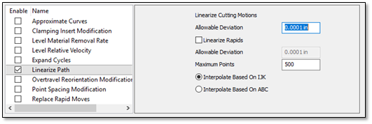
Allowable Deviation – The allowable chordal deviation of the actual 5-axis motion from the straight line relative to the part.
Linearize Rapids – Controls whether rapid motions are also linearized. When this option is enabled, it contains a separate Allowable Deviation which is applied to the rapid motion. That deviation can usually be set to a larger number than the cutting deviation.
Maximum Points – Set the maximum number of points that can be inserted for each move that is being linearized.
Interpolate Based On IJK – The interpolated points that are inserted will be calculated based on the change in the orientation vector relative to the part.
Interpolate Based On ABC – The interpolated points that are inserted will be calculated based on the change in the machine axis angles.
Overtravel Reorientation Modification – This modification will evaluate the path for overtravel’s on wrist type machines which do not have continuously rotating axes. For these machines, once the rotary reach it’s limit, it must lift off of the part, unwind to the opposite tilt/rotation, and then re-approach the part to continue machining.
WARNING – Consult with CAMplete Solutions BEFORE using this modification.
Min Rotary Angle – The minimum allowable rotary angle. When the angle goes past this angle, the reorientation will occur.
Max Rotary Angle – The maximum allowable rotary angle. When the angle goes past this angle, the reorientation will occur.
Retract Distance – Sets how far off of the surface the tool will retract before unwinding. (Note the tool always retracts and re-approaches along the orientation axis to avoid gouging the part).
Orientation Change Feed – Set the feed rate to use while re-orienting the spindle.
Unwind Rotary If Possible – This option will unwind the spindle back through the 0 degree mark to ensure that it does not overtravel.
Point Spacing Modification – This modification will evaluate the spacing of the positions in the tool path and modify them to be more consistently spaced.
WARNING – Consult with CAMplete Solutions BEFORE using this modification.
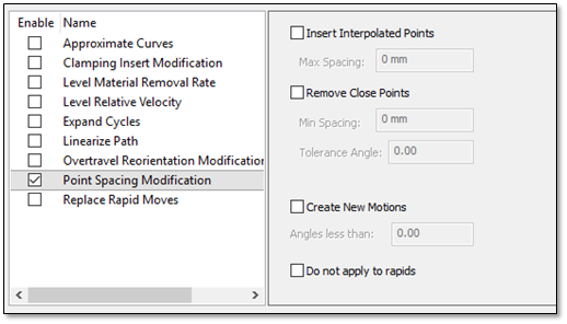
Insert Interpolated Points ** – This option will add interpolated points to the path to ensure that the **Max Spacing is achieved. This means that the maximum spacing of all positions after this modification is applied will be the Max Spacing.
Remove Close Points – This option works in the opposite and will remove points that are too close together based on the Min Spacing and Tolerance Angle (which checks for sharp corners before removing the point).
Create New Motions – Will create new tool motions for angles that are less than the specified value. That will break a raster path into multiple motions.
Do Not Apply to Rapids – This option will ignore rapid moves and only be applied to linear cutting moves.
Replace Rapid Moves – This modification will convert any rapid moves into feed moves. This can be helpful for older machines without linearized rapid moves.
WARNING – Consult with CAMplete Solutions BEFORE using this modification.
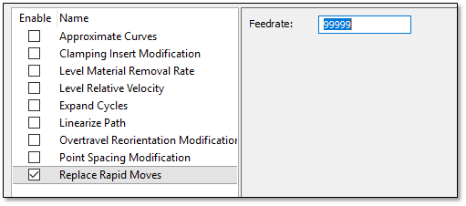
Feedrate – Sets the feedrate to be used instead of rapid moves.
Programs
The Programs pane shows the various program options:
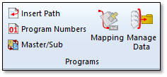
Insert Path– Will insert a blank tool path into the project. This is usually used to test machines with the Jog view.
Program Numbers – Show the Program Numbers view:
Click Program Numbers in the Ribbon interface to display the Program Numbers view:
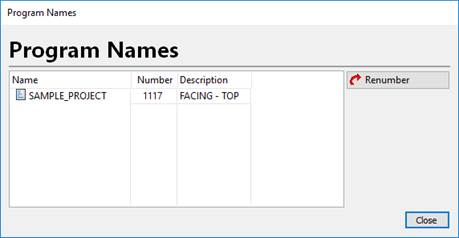
Each program is listed in the grid.
Name – Shows the name of the program as it appears in the Projects tree.
Number – Shows the program number. This number will be posted in the program G-Code as the program number code.
Description – Shows the program description, which can be posted as a comment or as an alphanumeric program name.
If multiple programs are selected, click Renumber to automatically adjust the program numbers sequentially.
- Note: Your NC Format must be set up to output the program number from this view.
Master/Sub– Will start the CAM Wizard and show the Master program page.
Mapping – Shows the program format mapping window.
Click Mapping on the ribbon interface to display the window:
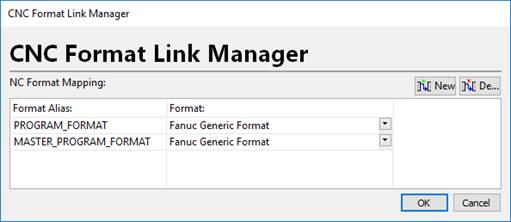
The PROGRAM_FORMAT entry lets you set the default NC Format that will be applied to any newly imported programs for this project only. Select the format in the Format column.
The MASTER_PROGRAM_FORMAT entry lets you set the default NC Format that will be applied to any newly created master programs for this project only. Select the format in the Format column.
Click New to create a new mapping and Delete to delete a custom mapping. The PROGRAM_FORMAT and MASTER_PROGRAM_FORMAT items cannot be deleted as they are default mappings.
- Note: To use custom default mappings, your CAM system must provide support for selecting the NC Format from the CAM data.
Manage Data– Shows the program data manager for very large paths. When programs are offloaded they will be in separate .PGM files, which you must manage individually.
WARNING – Consult with a CAMPLETE SOLUTIONS ENGINEER before using this feature.
Click Manage Data on the ribbon interface to display the Manage Tool Paths dialog:
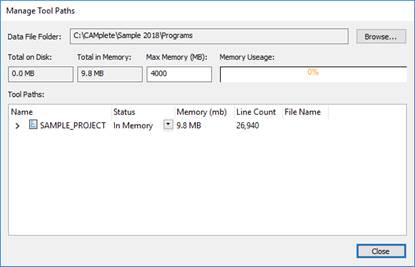
Data File Folder – Specifies where the offloaded data files are located. Use Browse to change this location.
Total on Disk– Shows the size of offloaded programs that are on the disk.
Total in Memory – Shows the total size of programs in the memory.
Max Memory – Specifies the maximum amount of memory for the Memory Usage bar graph.
Tools Paths – Lists the programs and their status:
a. Name – Name of the program or operation.
b. Status – Switch between In Memory and On Disk. When switched to On Disk, the file will be offloaded. Note that when you export a program to disk, it will no longer be saved in the CS4 project file. You will be responsible for copying the offloaded files from the Data File Folder location. When a program is offloaded, it cannot be used inside of TruePath but it will appear (as offloaded) in the Projects tree.
c. Memory – Estimated memory usage for the path
d. Line Count – Number of lines in the program or operation
e. File Name – Name of the offloaded file if the program is offloaded. These files a .PGM files and cannot be used outside of your project.
CAM Files
The CAM Files pane shows the various program regeneration options:
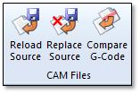
Reload Source – This option will reload an operation from the CAM file and replace the existing operation with the one from the CAM file.
Select the operation in the Projects tree and click Reload Source in the ribbon.
The Operation Reload dialog will be displayed:
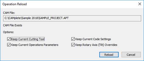
The original file will be displayed in the CAM file section.
Choose the reload options
a. Keep Current Cutting Tool – Will keep the currently assigned cutting tool (ignore the tool that would come from the CAM file)_
b. Keep Current Operation Parameters – Keep all current program parameters from the original operation.
c. Keep Current Code Settings – Will keep any user edited code settings, such as coolant and high speed modes. Only the tool path positions will be changed.
d. Keep Rotary Axis (Tilt) Overrides – Keep any user edited rotary axis overrides.
Click Reload to reload the path.
The operation will be reloaded from the CAM data and the program will be reposted with the new operation data.
Replace Source – This option will completely replace an operation from the CAM file with no options to keep any existing data.
Select the operation in the Projects tree and click Replace Source in the ribbon.
The new CAM file will be loaded and the operation will be automatically be replaced.
Compare G-Code – This option will compare any edited G-Code to the program in your project.
Select the program in the Projects tree and click Compare G-Code in the ribbon.
The Program G-Code Compare dialog will be displayed:
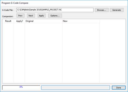
G-Code File - The name of the file you want to compare to. Click Browse to select a different file.
Click Generate to compare the files. The results will be displayed in the grid:
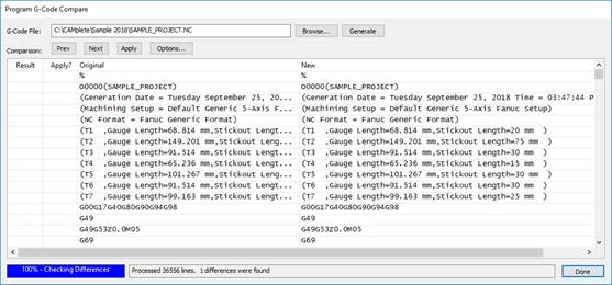
Result – Shows if there was a difference in the G-Code.
Apply? – Controls whether you want the difference to be applied back to the original program. This works for feed, speed and coolant mode changes.
Original – Shows the original G-Code.
New – Shows the new G-Code
Click Prev and Next to move back and forth between any lines that have differences.
Click Apply to apply any differences back to the program.
Click Options to see the comparison options:
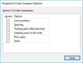
a. Line Numbers – Will ignore line number differences in the comparison.
b. Spacing – Ignore any spacing differences in the comparison.
c. Trailing zeros after decimal – Ignore any trailing zeros in numbers.
d. Leading zeros in M-Code – Ignore leading zeros in M and G-Code (G1 and G01 are the same).
e. Plus Signs – Ignore any plus signs on positive numbers.
f. Units – Ignore any unit differences.
Regeneration
The Regeneration pane shows the various program regeneration options:
Regenerate All – Regenerate any programs that are currently waiting for regeneration. This is controlled through Auto-Regeneration options. (see section User Preferences – Editor Page)
Re-Apply NC Formats – Show the NC Format Re-Apply window. This will force the NC Format to be re-applied. (see Re-Applying the NC Format to Existing Programs)
Export
The Export pane shows the various program export options:
Export – Will export the program(s) as G-Code. (See Exporting the G-Code Program(s) – Page 6)
Summary – Will display the Summary page in the CAM Wizard.
Analyze
The Analyze pane shows the 2D Graph button:

Click 2D Graph to toggle the graphing view ON and OFF:
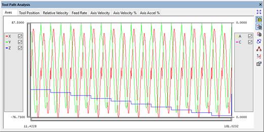
The graph shows a 2D plot of the current data that is in the tool path editor view.
Each data set is shown in the legend with a name and a color. Each data set that can be turned ON and OFF by clicking it’s check box:

The scales are shown in the left and right sides for left and right side data. As you move the mouse cursor, the appropriate data is displayed:
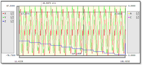
If you click on a position in the graph, you will be moved to the closest position in the simulation. The current simulation position is shown as a dashed line.
Use the mouse wheel to zoom in and out on the view. As you zoom, note that the scale bars on the left and bottom change to show you the zoom amount.
The buttons are:

Autoscale – Zoom out to see the entire 2D plot.

Lock Scale – Locks the scaling of the 2D plot.

Mouse Wheel Zoom in X – Enables zooming the X scale using the mouse wheel.

Mouse Wheel Zoom in Y – Enables zooming the Y scale using the mouse wheel.

Regen – Will redraw the data.

Show Data Points – Show each individual data point on the graph as a small box.

Graph Extra Info – Certain graphs, such as the Axes tab will show a dashed line whenever an axe reverses direction.

Graph Properties – Edit the properties of the graph. This lets you adjust the colors of the various plotted data.
Each tab shows a different set of data:
Axes
Shows the machine axes. The linear axes are on the left and the rotary axes are on the right.
Tool Position
Shows the tool position in cutter location coordinates. The XYZ of the tool center is on the left and the IJK orientation vector is on the right.
Relative Velocity
Displays the relative velocity of the tool motion relative to the part X, Y and Z axes and overall velocity.
Feed Rate
Displays the programmed feed rate.
Axis Velocity
Displays the velocity of each machine axis.
Axis Velocity %
Displays the velocity of each machine axis as a percentage of the maximum velocity of that axis.
Axis Accel %
Displays the axis acceleration for each axis.
Axes – Shows the machine axes. Each axis position is plotted. The left hand scale is for the linear axes. The right hand scale is for the rotary axes.
The 2D Grp All – Regenerate any programs that are currently waiting for regeneration. This is controlled through Auto-Regeneration options. (See User Preferences – Editor Page - Page 6)
Windows
The Windows pane shows the toggle buttons for the Program Editor and Regeneration Window:

Program Editor – Toggle the Program Editor view On and Off.
Regeneration Window – Toggle the Regeneration Window On and Off.
