
Autodesk CAMplete TruePath can simulate the material removal process during machining to show the finished part. The stock material simulation is only done in Collision Check mode or Optimization mode. You will not see collision checking or material removal performed in Real Time mode.
Managing Stock Material for Machining Simulation
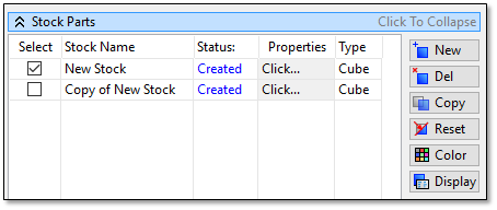
The stock parts are managed through the Pallet View, which is usually docked as a tab to the Project Navigator view:
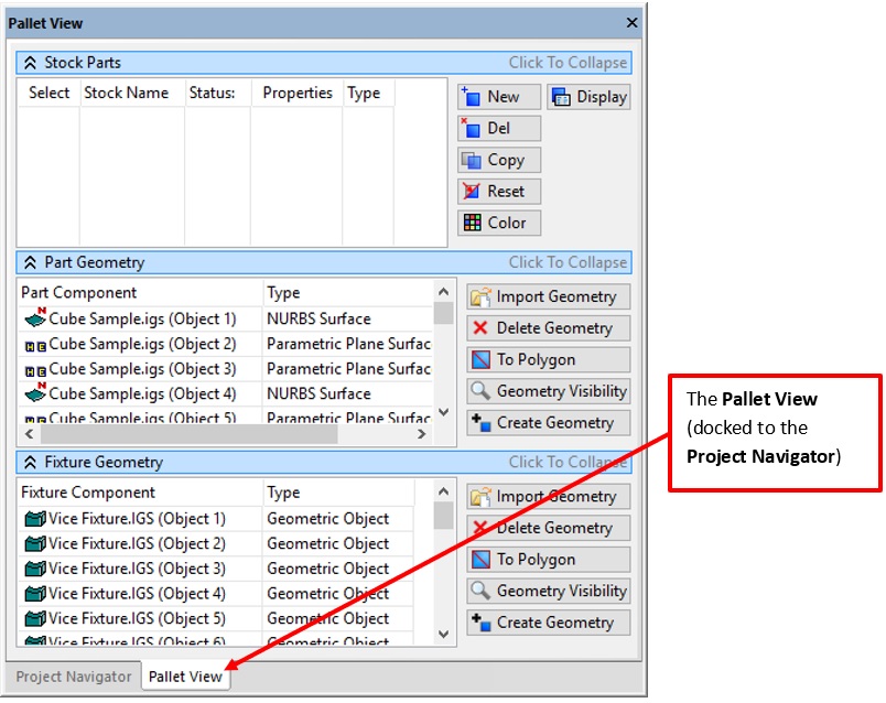
The stock parts are listed in the Stock Parts grid.
The columns for each stock part are:
Select – Sets the active stock part (the one that will be displayed in the 3D view and used for simulation). Only 1 stock part can be active at any time. You can also have no active part selected as active.
Stock Name – Shows the user editable name of the stock.
Status – Shows whether the actual stock geometry has been created (as opposed to just the settings being edited).
Properties – Click to show the properties dialog of the given stock part.
Type – Shows the type of stock (Cube, Cylinder, Profile or Polygon).
The buttons can be used for quicker access:
New – Create a new stock part.
Del – Delete the currently selected stock part in the grid.
Copy – Copy the currently selected stock part in the grid.
Reset – Reset the currently active stock part (i.e., the part that has its Select item checked).
Color – Edit the colors for the stock part.
Display – Edit the current display properties of the currently active stock part (ie. the part that has its Select item checked).
Creating a Block Stock Part
Click New to add a new stock part.
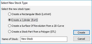
The Select New Stock Type dialog will be displayed:
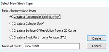
Select the Create a Rectangular Block option and enter a name.
Click Create.
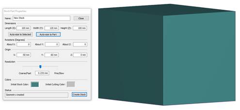
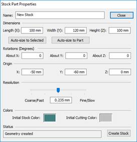
The Stock Part Properties dialog for the rectangular block will be displayed:
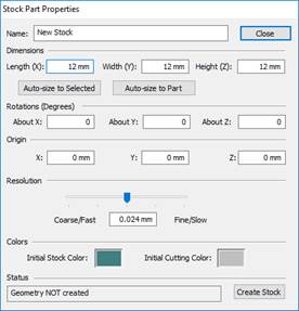
Name – The name of the stock part.
Length, Width and Height – The size of the block.
Rotations About X, About Y and About Z – Rotate the block around each axis.
Origin X, Y and Z – Set the lower left location of the block.
Click Auto-size to Selected to set the values to the currently selected objects in the 3D view. Note that when you do this, the rotations will be reset to 0.
Click Auto-size to Part to set the values to the current part geometry. Note that when you do this, the rotations will be reset to 0.
The Resolution slider sets the size of the material removal “cubes”. Setting this to a larger value will create a more coarse resolution but will simulate faster. Setting it to a smaller value will create a finer resolution but will simulate slower. Putting the slider in the middle position is recommended for the best combination of resolution and speed.
The Colors set the Initial Stock Color (uncut stock) and the Initial Cutting Color (for the first stock that is cut).
Click Auto-size to Part to set the stock to the part size.
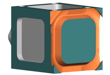
As changes are made to the values, a preview is shown in the 3D view:
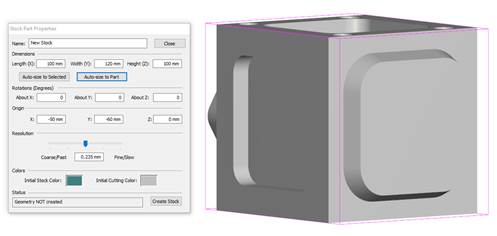
Click Create to create the block.
The new block will now appear on the screen and in the stock list:
Click Close to close the properties.
The New Stock part will appear in the grid and will be the active stock part.
Copying a Stock Part
Select the stock object in the grid.
Click Copy.
A new copy of the stock object will appear in the grid:
 Note: The new copy is not active (selected in the Select column).
Double click its name in the Stock Name column to set a new name.
For this example, click its Select column to make it active.
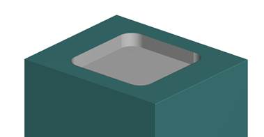
Now run the simulation (in Collision Detection mode, since that is the mode where material removal is performed).
You will see the material being removed:
Adjusting the Display Properties
After a simulation is run, you can adjust the display of the cut stock.
Click Display on the Stock View.
The current properties of the active stock part will be displayed:
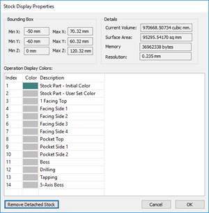
The various properties of the stock part will be displayed in the Bounding Box and Details section.
Each toolpath, specified in the Description column of the grid, can be displayed with a unique color.
The Stock Part – Initial Color is the color of the un-cut stock.
The Stock Part – User Set Color is the current color.
To change any of the colors, double click the color in the grid and select a new one.
After selecting your colors, click OK.
The stock part will be displayed with the given colors:
Resetting the Stock Part
After running a simulation the active stock part can be reset to its original settings.
Click Reset on the Stock View.
You will be prompted before your stock part is reset:
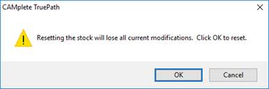
Click OK and the stock part will be reset.
Editing a Stock Part
The stock part properties can be adjusted at any time.
Select the stock part in the grid and click in the Properties column.
The Stock Part Properties for that stock part will be displayed:
Note that the Status column will now say Geometry Created, indicating that the stock geometry is created.
You can adjust any setting, just as if you were making a new stock part.
To create the stock with the new settings, click Create Stock. Note that you will be warned that the existing stock geometry will be lost (since the part is being recreated).
Deleting a Stock Part
Stock parts can be deleted through the stock view.
Select the part in the Stock View grid. (It does not need to be the active one).
Click Del.
The part will be deleted from the grid and the 3D view.
Creating a Cylinder Stock Part
Cylindrical stock parts can be created directly from the Stock View.
Click New on the Stock View.
Select Create a Cylinder from the Select New Stock Type dialog:
The Stock Part Properties for a cylinder will be displayed:
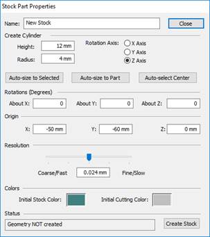
Height and Radius – Set the size of the cylinder.
Rotation Axis – Set the alignment axis for cylinder center (around X Axis, Y Axis or Z Axis) when originally created.
Rotations About X, About Y and About Z - Rotate the cylinder about the given axis.
The Origin X, Y and Z determines the bottom center location of the cylinder.
Click Auto-size to Selected to set the values to the currently selected objects in the 3D view. Note that when you do this, the rotations will be reset to 0.
Click Auto-size to Part to set the values to the current part geometry. Note that when you do this, the rotations will be reset to 0.
The Colors set the Initial Stock Color (uncut stock) and the Initial Cutting Color (for the first stock that is cut).
The Resolution slider sets the size of the material removal “cubes”. Setting this to a larger value will create a more coarse resolution but will simulate faster. Setting it to a smaller value will create a finer resolution but will simulate slower. Putting the slider in the middle position is recommended for the best combination of resolution and speed.
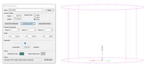
A 3D preview of the cylinder will be displayed in the 3D view:
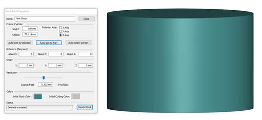
Click Create to create the cylinder. The cylinder geometry and stock part will appear:
The cylindrical stock part can be managed in the same manner as the block stock part (properties, copy, reset and delete)
Creating a 2D Revolved Profile
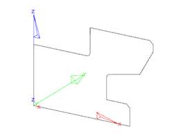
For symmetrical parts made from a revolved profile, you need to have a 2D closed and joined curve. The curve must also be all on one side of the XY, YZ or ZX quadrant.
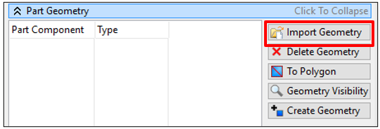
On the Pallet View > Part Geometry section click Import Geometry:
Select an IGES file that contains the target curve that will be revolved. The geometry will appear in the grid and in the 3D view:
Click New on the Stock View.
Select Create a Surface Of Revolution from a 2D Curve from the Select New Stock Type dialog:
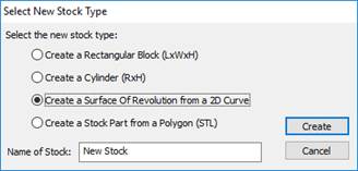
Click Create.
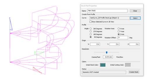
The Stock Part Properties dialog will be displayed for the 2D profile revolution:
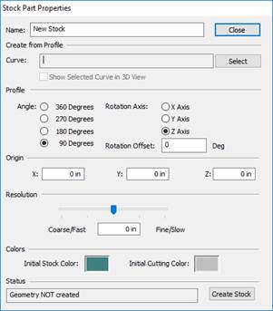
Curve - The currently selected source curve. At this point, nothing will be shown here since no curve has been selected.
Profile: Angle – Controls how much of the revolution will be performed (90, 180, 270 or 360).
Profile: Rotation Axis – Sets the axis about which the curve will be revolved.
Profile: Rotation Offset – Rotates the final stock material around the rotation axis. This can be used to get the stock positioned in the correct location if using on the 90/180/270 revolutions.
Origin – Sets the center of the revolution in X, Y and Z.
Resolution - Sets the size of the material removal “cubes”. Setting this to a larger value will create a more coarse resolution but will simulate faster. Setting it to a smaller value will create a finer resolution but will simulate slower. Putting the slider in the middle position is recommended for the best combination of resolution and speed.
Colors - Set the Initial Stock Color (uncut stock) and the Initial Cutting Color (for the first stock that is cut).
In the 3D view, select the source curve using the mouse. (You can also select it in the Part Geometry grid and it will highlight in the 3D view)
Click Select in the Stock Part Properties.
You will be prompted to Delete the original curve:
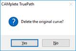
Answer Yes to this question.
The name of the curve will now appear in the dialog.
And 3D preview of the revolved surface will be displayed in the 3D view:
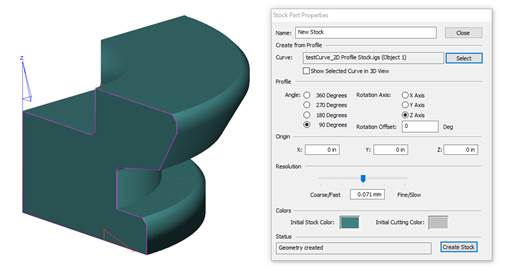
Click Create Stock to create the stock part.
Note: this may take a few minutes depending on the complexity of your source curve.Your stock part will now appear in the 3D view and in the stock part list:
Creating a Stock Part from an STL file
For non-standard shapes parts made from STL files can be used to define the stock volume.
Click New on the Stock View.
Select Create a Stock Part from a Polygon (STL) from the Select New Stock Type dialog:
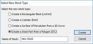
Click Create.
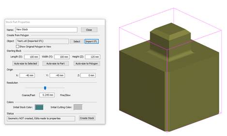
The Stock Part Properties dialog will be displayed for the 2D profile revolution:
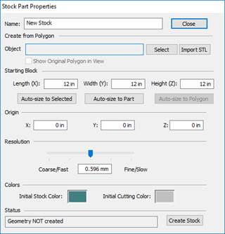
Object - Shows the currently selected STL object. At this point, nothing will be shown here since no object has been selected.
Starting Block – Defines the Length, Width and Height of the starting block. When the actual geometry is created, it will be “clipped by this block:
Origin – Sets the center of the starting block in X, Y and Z.
Resolution – Sets the size of the material removal “cubes”. Setting this to a larger value will create a coarser resolution but will simulate faster. Setting it to a smaller value will create a finer resolution but will simulate slower. Putting the slider in the middle position is recommended for the best combination of resolution and speed.
Click Import STL and select the STL file for the stock shape.
The name of the STL object will now appear in the dialog.
The 3D preview of the clipping box will be displayed in the 3D view:
Use Auto-Size to Polygon to set the starting block to the dimensions of your source polygon.
Note: The stock will be clipped by the starting block. For example, if you select half the box, it will result in: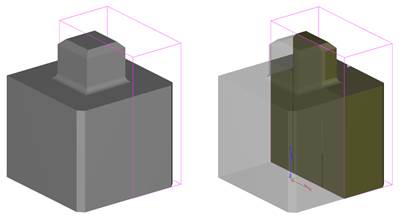
Click Create Stock to create the stock part.
Note: this may take a few minutes depending on the complexity of you source polygon.Your stock part will now appear in the 3D view and in the stock part list