Machining Setup Manager
Now that you have created a custom tool assembly and NC format, you can tie everything together by creating a custom machining setup.
To access the Machining Setup Manager, click Machines on the Manage tab:

This accesses the Machines page of the Resource Manager. Alternatively, you can access the Resource Manager using the Resources button at the bottom of the Project Navigator view:

The Resource Manager > Machines page lets you view and manage your machining setups (ie. Your machine models).
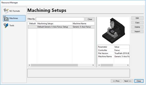
To copy and customize a default machining setup
In the machining setup list, select the machine you want to copy.
Click Copy and a new machine will appear with the same name but with “ – Copy #1” added to the name.
Select the new copy in the list.
Click Edit to launch the Machining Setup Editor:
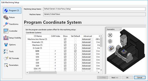
Modifying the Machining Setup Name
Enter a new name for the machining setup. For this example, enter the name “Demo Machining Setup”:

Adjusting the Setup Visibility
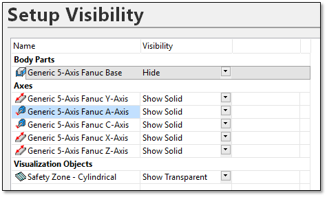
You can hide and show the different parts of the machine through the Setup Visibility page. Thus you can control how the machine looks by default.
Go to the Visibility Page.
Modify the Visibility setting for each part of the machine.
For this example, you can hide the base and enclosure geometry (if applicable):
Adjusting the Machine Options
Some machines have optional components that can be enabled. These can be things like laser measurement devices or alternative work tables.
Click Options to access the machine options page.
To disable or enable any options click the On/Off column:
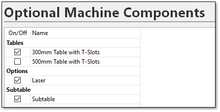 Note: As you change the options, the update will be shown in the 3D preview. There may be a delay as the new geometry is reloaded.
To customize the default tools in the tool changer:
Your machining setups can be preloaded with tooling setups that accurately match the physical tooling you use. Preloading tools in your machining setup allows Autodesk CAMplete TruePath to automatically replace tools loaded from your CAM files when an appropriate tool is available.
Click Tools to access the Tool Changer properties for the machine.
Click New Tool.
Select the tool assembly “Demo 50 mm Bullnose (5 mm rad)” you created earlier.
Double-click the tool number for the assembly in the grid.
Type 10 in the Tool Number field and press Enter.

You can also specify a Default Holder that will automatically selected whenever tools are loaded that contain no tool holder info. This can be selected by clicking Change and selecting the new default holder from your database of holders.
To assign a default NC Format to the machining setup
You can configure your machining setups to use a default NC format. Autodesk CAMplete TruePath automatically selects the default NC format for you every time you use this machining setup.
Click NC Formats to access the Default NC Format Properties page.
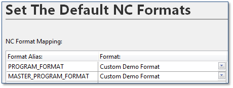
Select the NC format you created earlier as the Default NC Format for Programs.
For this example, select the “Custom Demo Format” as the default:
To complete the changes to the Machining Setup
Once you are finished modifying the machining setup, you need to commit the changes.
Click OK to close the machining setup editor.
If you are alerted that an existing file will be overwritten, click Yes.
Any time you edit an existing machining setup without changing the name, you will be prompted that an existing file will be overwritten. This warning allows you to cancel the save process if you decide not to save your settings. If you do not click Yes, any changes you have made will not be saved.
If you changed the name of the machine, the update will be reflected in the machine list.
Once the Machining Setup Manager has been closed the changes will affect loading new projects.
Close any open documents and reopen the sample CAM file.
In the CAM Import Wizard, select the custom machining setup you created.
Go to the NC Format page. Note that the Custom Demo Format has automatically been selected.
Go to the Tools page. Note that instead of using the tool created from the APT file, the application has substituted Tool 10 from the machine’s tool changer.
Click Finish and select the project to see all of your tool paths in the Tool Path Editor.
