Autodesk CAMplete TruePath uses a Status view to efficiently navigate through application messages, warnings and errors.
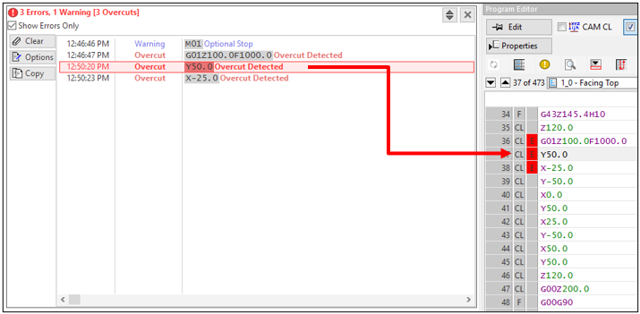
The Status view shows the current applications errors and messages:

By default, the Status view will be in the collapsed state. If there are errors or warning, they will be shown in the summary.

Clear – Clear the current status and error messages from the view.

Options – Access the status options dialog.

Copy – Copy the selected status lines to the Windows Clip board for easy pasting into a document, email or text editor.

Collapse/Expand – Toggle the status window between compact and expanded mode.

Close – Close the Status view.
Note: If new errors are reported, the status view will reappear automatically.NOTE: To re-show the Status view, go to the Manage tab in the Ribbon and click Status View.Expand the Status view to see the specific errors:

By default, only the errors and warnings are shown. Un-check the Show Errors Only option in order to see all logged applications messages.
The error grid shows the time of the error, the type of error and the G-Code and details about the error. The G-Code of the line is shown in grey high-lighted text for easy viewing.
When errors occur during simulation, double click the line to go that line in the status view (Note that the status line will show the actual G-Code).

- Warning:Sometimes an error message refers to a line that is no longer in the program editor. This can happen when you switch the currently simulating program in the Project view, or if the program is deleted, or if the line was lost during a format change. When this happens and you double click an error message, you will see this warning:

If you have the Stop? option enabled for that error, then the Simulation Error dialog will also be displayed and the simulation will be temporarily stopped:

The location of the error is reported in the top edit box (the name of the operation and program).
The G-Code Line shows which line is causing the error. The actual error is listed in the grid.
The grid columns are:
Error – Shows the name of the error that occurred.
Level – Shows the type of error (either a warning, error or critical error).
More Details – Click to show more details about the error that occurred.
Stop? – Controls whether the simulation will stop and show the Simulation Error dialog when that error occurs.
Description – A description of the error.
In this example, click More Details on the Overcut error. The info on the Overcut would be displayed:

Click OK to close the Error Details dialog.
If you no longer want to stop the simulation and show this dialog for that particular error, you can uncheck it’s Stop? option column:

At this point, if you click Stop Simulation the simulation will be stopped. Note that any changes you made to the Stop? column would not be applied.
Click Continue to keep simulating. Note that if you un-check the Stop? option, the Simulation Checks on the main Simulation Options section of the Ribbon will switch to WARN instead of STOP:

Note that the Stop? option ONLY controls whether the simulation will be stopped. If the Check is ON, the error will still be reported in the Status view.
Over-Travel Errors
Over-travel errors will be reported now with the name of the over travelling axis listed:

Also, the Simulation Error dialog will show the same info:

If you click More Details for Over-Travels, you will see this dialog:

Other Simulation Errors
Other simulation errors will be reported in the same dialog. For example, Rotation During Tilted Plane errors would appear as:

If you change the Stop? setting for these errors, the error will still be reported but the simulation will no longer stop. To control the Stop? setting for any of these errors, click Advanced on the Simulation Options panel of the Real-Time/Collision Check/Optimization tab in the Ribbon:

This will show the Simulation Options dialog. Switch to the Errors page and each option can be controlled through the Stop? column:

Multiple Errors on the Same Line
Autodesk CAMplete TruePath will distinguish between collisions (where components collide with one another), proximity violations (where components are too close to each other) and overcuts (where the cutting tool gouges the part.
When a line causes multiple errors, each will be listed in the Simulation Error dialog:

The Stop? status for each error type will match your current options.
The More Details item can be clicked to see each individual error.
The Error Summary View
The Error Summary view allows you to see the status of your program with a quick glance. It will tell you which programs and operations have been verified and what errors and warnings were found (if any).
The Error Summary can be found on the Simulation View tab of the ribbon.

This will toggle the Error Summary view:

Each program and its operations are listed in the top grid. The top grid shows a summary of:
Operation: The currently selected operation and program(s). Programs can be expanded in the tree or the Collapse button can be used to control whether programs are expanded or collapsed by default.
Lines: Shows the total number of lines in the program or operation.
Status: Shows the simulation status of the program or operation. This shows how many lines have of the object have been simulated. If less than 100% has been checked, this appears in yellow, as a warning.
Errors: Shows the total number of simulation errors that were found (not including collision, over-travels, over-cuts and proximity violations).
Overtravels: Shows the total number of over-travels that were found. This will appear in red if any over-travels were detected.
Collisions: Shows the total number of collisions that were found. This will appear in red if any collisions were found.
Overcuts: Shows the total number of collisions that were found. This will appear in red if any collisions were found. This will appear in yellow if overcut detection was not enabled during the simulation.
Prox (All): Shows the total number of Proximity All violations that were found. This will appear in red if any violations were found. This will appear in yellow if Proximity All detection was not enabled during the simulation.
Prox (Tool/Part): Shows the total number of Proximity Tool/Part violations that were found. This will appear in red if any violations were found. This will appear in yellow if Proximity Tool/Part detection was not enabled during the simulation.
Prox (Tool/Fixture): Shows the total number of Proximity Tool/Fixture violations that were found. This will appear in red if any violations were found. This will appear in yellow if Proximity Tool/Fixture detection was not enabled during the simulation.
Each Status item will be displayed in yellow if the particular option was not checked OR if the entire operation/program was not simulated.
You can click Collapse to collapse the program items in the tree.
The Error Summary view is modeless, so it can be left open while you navigate through your program.
If you select an operation in the upper grid (not a program), each error in that operation (path) will be summarized in the lower grid:

Index: The error index in the list of errors.
G-Code: The G-Code of the line that caused the error.
Errors: Shows any error that was found for the line.
Overtravels: Shows if the line was an over-travel.
Collisions: Shows if the line was a collision, and which objects collided.
a. Overcuts: Shows if there was an over-cut on the line.
b. Prox (All): Shows if there was a Proximity All violation and which parts were involved.
c. Prox (Tool/Part): Shows if there was a Proximity Tool/Part violation.
d. Prox (Tool/Fixture): Shows if there was a Proximity Tool/Fixture violation.
As you select each line in the lower grid, you will be taken to that line in the simulation.
You can filter out particular errors using the check boxes at the top of the lower grid.
As you highlight errors in the lower grid, the Error Details will show you more info about the error (if applicable).
