The 3D View can be controlled through the 3D View tab of the Ribbon interface.

View
The View panel allows you to interact and control the current 3D View.
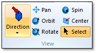
Direction – Set the direction of the view (this drops down a menu).
Pan – Switch to pan mode (left click with the mouse to pan the view).
Orbit – Switch to orbit mode (left click with the mouse to orbit the view). Orbit adjusts the azimuth angle with the left and right motion of the mouse and adjusts the elevation with the up and down motion.
Rotation – Switch to rotation mode (left click with the mouse to orbit the view). Rotate adjusts the rotation angle around the Y view axis with the left and right motion of the mouse and adjusts the rotation angle around the X axis with the up and down motion.
Spin - Switch to spin mode (left click with the mouse to spin the view around the view axis).
Center – Center the view on the currently selected object.
Select – Switch to select mode (select objects in the 3D view using the mouse). This is the default mode.
View Properties
The View Properties allow you to adjust the lighting, views and background display.
Click View Properties:

The 3D View Properties view will be displayed.
Go to the Lighting page:
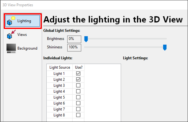
Global Light Settings control the overall lighting level.
Adjust the Brightness slider to make all lighting brighter or darker. 0% means that the brightness is not being adjusted.
Adjust the Shininess slider to control how shiny each object is in the view.
Individual Lights shows each of the 8 available lights in the view.
Each light is listed in the view. Click Use? to turn the light ON or OFF.
To show the light in the 3D view, enable the Draw option in the column.
When you select a light, its settings are shown to the right:

Light Position – The location of the light. If Relative To View is clicked, the light will be position relative to the view. To move the light directly in the 3D view click Move Tool.
Diffuse – Sets how much diffuse light is emitted from the light. This is the light that makes objects appear shiny.
Switch to the Views page.
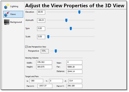
Elevation – Set the current elevation angle of the view.
Azimuth – Set the current azimuth angle of the view.
Spin – Set the spin angle around the view direction.
Scale – Set the scale of the current view.
Use Perspective View – Control the amount of perspective being applied to the view.
Viewing Volume – The width, height, near and far viewing distances.
Target and Pan – The current center of the view in XYZ coordinates and the pan in X and Y.
Switch to the Background page:

Default Background – Set the color of the background.
Use Gradient – Use a second color to blend the background as two colors.
Switch – Switch the background and gradient colors.
Luminance – Adjust the color from brighter to darker.
Wireframe and Shaded view
Use the Wireframe and Shaded buttons to switch the 3D display mode.

Adjust the Brightness
You can quickly adjust the brightness without using the View Properties window:
Click Brightness.

The Brightness window will be displayed:

Adjust the Brightness slider to make all lighting brighter or darker. 0% means that the brightness is not being adjusted.
Adjust the Shininess slider to control how shiny each object is in the view.
Adjust the Background
You can quickly change the background with using the View Properties window:
Click Background.

The Brightness window will be displayed:

Default Background – Set the color of the background.
Use Gradient – Use a second color to blend the background as two colors.
Switch – Switch the background and gradient colors.
Luminance – Adjust the color from brighter to darker.
Zoom
The Zoom panel provides several ways to zoom the view.
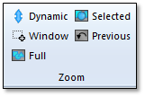
Dynamic – Switch to dynamic zoom mode (left click and move the mouse to zoom the view in and out).
Window – Zoom to a window selected by the mouse.
Full – Zoom out to show all of the objects in the view.
Selected – Zoom to show the currently selected objects in the view.
Previous – Go to the previous view.
Objects
The Objects panel provides several ways to interact with objects in the 3D view.
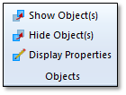
Show Objects – Show the currently selected object(s) in the 3D View.
Hide Objects – Hide the currently selected object(s) in the 3D View.
Display Properties – Access the display properties for the currently selected object(s).
Clipping Planes
The Clipping Planes panel provides several ways to control the display of the part and fixture geometry using clipping planes to slice the part.
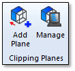
Add Plane – Add a new clipping plane to the part or fixture.
Manage – Mange the current clipping planes.
Click Add Plane to add a new clipping plane.
The clipping plane editing dialogs will appear along with a plane that can be manipulated directly in the 3D view:
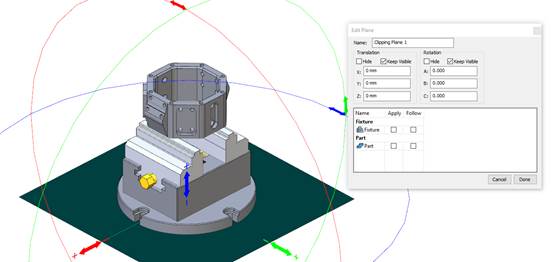
In the Edit Plane dialog, enter the name of the plane.
Then choose whether the plane should clip the part and/or fixture.
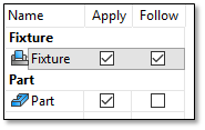
Click Follow to choose that the plane should move with the part or fixture during the simulation
In the 3D view, manipulate the plane. One side of the plane will slice the part. The other side will be shown:
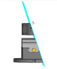
When completed, click Done to close the plane editor.
The part and/or fixture will now appeared sliced, so you can inside the part and fixture:
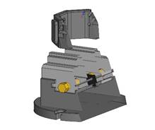
To edit any existing panes click Clipping Planes > Manage.
The manage dialog will be displayed:
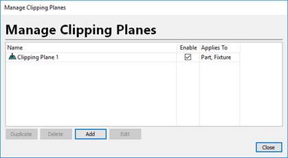
Each Clipping Plane will be listed.
To change a name double click the Name column.
Use the Enable column to turn the clipping plane ON and OFF.
To edit a plane, select it and click Edit.
To delete a plane, select it and click Delete.
To make a copy of a plane, select it and click Duplicate.
Click Add to create a new clipping plane.
Selection
The Selection panel controls how objects are selected in the 3D view.
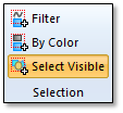
Filter – Controls what kinds of objects can be selected. By default, all objects are selectable. The
By Color – Select objects in the 3D view by their color.
Select Visible – By default, only the top visible object will be selected in this mode when the mouse left button is clicked. If this mode is off, all objects under the mouse will be selected, regardless of whether it is the top object under the mouse. (Hidden objects are not selectable in the 3D view).
Construction Pane
The Construction Pane panel controls how the construction plane behaves in the 3D view.
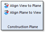
The construction pane is always shown in the lower left corner of the view. By default, it is aligned to the XY plane:

Align View to Plane – Align the current view to the construction plane.
Align Plane to View – Align the construction plane to the current view.
Analyze Pane
The Analyze Pane panel contains the Measure 3D command:

This will display the 3D Analysis dialog.

This dialog can measure 2 points in the 3D view and show the XYZ size and distance between the points.
Click Pick to select the first point.
The Pick 3D Point tool will be launched:

You can select a point in the 3D view. Its coordinates will appear in the tool bar.
You can manually edit the XYZ coordinates.
Click
 to select the center of a circle from 3 points.
Click
 to center the view on the current XYZ point.
Click
 to select that as the first point.
Repeat this process for the second point.
The 3D Analysis dialog will show the DX, DY and DZ distances between the 2 points. The Dist entry shows the distance between the two points.
Click 3D Box to show a 3D box between the 2 points:
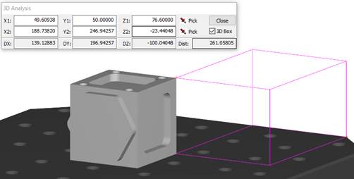
Click Close to exit the 3D Analysis tool.
Extras Pane
The Extras panel provides some extra control over the 3D view.
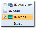
3D Aux View – Toggles the 3D Aux View which shows an alternative view of the project.
3D Scale – Control the 3D Scale overlay in the 3D view. (see 3D Scale)
3D Icons – Toggle the 3D icons in the view ON and OFF.
3D Scale
The 3D Scale in the 3D view to help with visualization of the current zoom factor:

This shows the scale of 1 unit on the screen (it’s the Width of the scale). In the above example, the “ruler” is 175.032 mm long.
To set the scale properties:
Click 3D Scale in the Extras panel.
The View Scale Properties dialog will be shown:
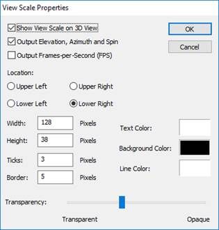
Show View Scale on 3D view – Enables or disables the scale ruler. Un-check this to hide the scale ruler.
Output Elevation, Azimuth and Spin – Shows the current Elevation, Azimuth and Spin angles for the view (in degrees).
Output Frames-per-Second (FPS) – Output the current 3D view frames per second (drawing speed) which can be useful for checking your video card performance.
Location – Set the location of the ruler to the Upper Left, Upper Right, Lower Left or Lower Right.
Width, Height – The width and height of the rulers in screen pixels.
Ticks – The number of ticks on the ruler.
Border – The border of the ruler relative to the edge of the screen in screen pixels.
Text Color – The color of the text in the ruler.
Background Color – The background color of the ruler.
Line Color – The line color of the ruler (for the border and pixels).
Transparency – Set the level of transparency for the ruler.
After modifying the options, click OK to close the dialog and apply the new settings.
