This topic contains details on the conversion of data in the [MOUSE_TABULAR_DATA], [MOUSE_CROSS_SECTIONS] and [MOUSE_TOPOGRAPHY] groups of the UND file.
Tabular Data [MOUSE_TABULAR_DATA]
This section holds sets of data connected to pump characteristics, weirs, passive flow control, emptying storage nodes, QH-relations and other types of data.
|
MOUSE |
Description |
InfoWorks ICM Data Field |
||||||||||||||||||||||
|---|---|---|---|---|---|---|---|---|---|---|---|---|---|---|---|---|---|---|---|---|---|---|---|---|
|
DATASETID |
Dataset name |
Used to identify the object with which the tabular data is associated. |
||||||||||||||||||||||
|
TYPENO |
Type of data in table:
|
|
||||||||||||||||||||||
|
DATA |
Data values:
|
See above |
Cross Section Data - [MOUSE_CROSS_SECTIONS]
Data in the [MOUSE_CROSS_SECTIONS] group of the UND file is imported into the InfoWorks ICM Conduit Shape table as a user defined shape.
|
MOUSE |
Description |
InfoWorks ICM Data Field |
||||||||||||||
|---|---|---|---|---|---|---|---|---|---|---|---|---|---|---|---|---|
|
CRSID |
Cross Section name |
Shape ID |
||||||||||||||
|
TYPENO |
Type of data
|
Not imported. The MOUSE type number defines whether the shape is open or closed. |
||||||||||||||
|
DESCRIPTION |
Cross section description |
Description |
||||||||||||||
|
DATA |
Raw data describing geometry in (Height, Width) format, or (X, Z) format. |
Imported for MOUSE cross sections, HWclosed, HWopen, XZclosed and XZopen. Height and Width values are imported to Height and Width arrays in Shape object. Height and width values are adjusted to fall between 0 and 1. |
||||||||||||||
|
PROCESSDATA |
Calculated height, width, area and hydraulic radius used in MOUSE hydraulic simulations. |
Imported for MOUSE cross sections, ProcClosed and ProcOpen Height and Width values are imported to Height and Width arrays in Shape object. Height and width values are adjusted to fall between 0 and 1. |
Channel Topography Data - [MOUSE_TOPOGRAPHY]
|
MOUSE |
Description |
InfoWorks ICM Data Field |
|---|---|---|
|
CRSID |
Cross Section name |
MOUSE Topography Cross Sections are imported as InfoWorks ICM Channel Sections. See Converting MOUSE Natural Channels into InfoWorks ICM Channel Sections below. |
|
CHAINAGE |
Distance from start of link that cross section is associated with. |
|
|
BOTTOMLEVEL |
The bottom level of the cross-section. |
|
|
MANNINGTOP |
Manning number at top of link |
|
|
MANNINGBOTTOM |
Manning number at bottom of link |
|
|
MANNINGEXP |
Exponential coefficient for Manning number |
Converting MOUSE Natural Channels into InfoWorks ICM Channel Sections
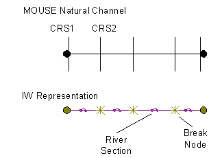
 MOUSE provides a link type of 'Natural Channel'. The natural channel is given a topography ID. The topography ID is linked to n number of cross-sections which can be specified along the length of the link. Cross-sections are provided at various lengths along the natural channel, including length 0.0 and the length of the pipe.
The MOUSE cross section data for natural channels is imported into InfoWorks ICM as follows:
- InfoWorks ICM creates a channel link for each cross-section excluding the last section, with the channel links separated by break nodes.
- The Cross Section data is imported into the Channel X Coordinate and Depth arrays of the InfoWorks ICM Channel shape grid. Depths are adjusted so that there is a 0.0 value in the InfoWorks ICM cross-section data e.g. if the lowest depth is 10.0, then subtract 10.0 from all depths.
- The MOUSE topography parameters are applied to the length of the channel link (rather than being interpolated with the next cross-section as is the case in MOUSE). In MOUSE, roughness is provided for the top and the bottom of the channel, whereas in InfoWorks ICM, roughness varies across the channel. InfoWorks ICM will take the mean of the top and bottom roughness and apply this to the channel.
- The first channel link will be given the upstream headloss coefficient of the MOUSE upstream manhole, provided that the coefficient is the total headloss coefficient (see Note on Headloss Coefficient Calculations) and the last link will be given the InfoWorks ICM default downstream headloss coefficient. All upstream and downstream headloss coefficients in between will be given a headloss type of 'fixed' and a value of 0.0 as the links inbetween are purely artificial.
