This subassembly widens an existing divided highway by extending from the travel lane edges inward over a depressed median, with a symmetrical barrier at the centerline. The median slopes may vary somewhat from the existing slopes to make both sides meet at the centerline, or to hold the top of the barrier to a profile.
Attachment
The attachment point is at the midpoint of the base of the barrier.
Input Parameters
Note: All dimensions are in meters or feet unless otherwise noted. All slopes are in run-over-rise form (for example, 4 : 1) unless indicated as a percent slope with a “%” sign.
|
Parameter |
Description |
Type |
Default |
|---|---|---|---|
|
Overlay Depth |
Thickness of the median overlay layers. |
Numeric, positive |
0.100 m 0.3 ft |
|
Slope Tolerance |
Amount that the median % slopes are allowed to vary from the calculated existing Left and Right slopes. |
Numeric, positive |
5% |
|
Left Insert Offset |
Offset where the median extension layer begins on the left side. |
Numeric |
0.0 |
|
Left Inside Sample Offset |
Offset of the inside sample point on the left side. The slope of the left side is calculated on the existing surface between the sample points. |
Numeric |
0.0 |
|
Left Outside Sample Offset |
Offset of the outside sample point on the left side. The slope of the left side is calculated on the existing surface between the sample points. |
Numeric |
0.0 |
|
Right Insert Offset |
Offset where the median extension layer begins on the right side. |
Numeric |
0.0 |
|
Right Inside Sample Offset |
Offset of the inside sample point on the right side. The slope of the right side is calculated on the existing surface between the sample points. |
Numeric |
0.0 |
|
Right Outside Sample Offset |
Offset of the outside sample point on the right side. The slope of the right side is calculated on the existing surface between the sample points. |
Numeric |
0.0 |
|
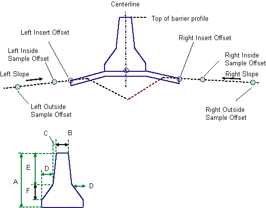
Dimension A (mm or inches) |
Height of the barrier from the base on the high side of the median to the top of the barrier. |
Numeric, positive |
810 mm 32 in |
|
Dimension B (mm or inches) |
As shown in diagram. |
Numeric, positive |
232 9 in |
|
Dimension C (mm or inches) |
As shown in diagram. |
Numeric, positive |
59 mm 2 in |
|
Dimension D (mm or inches) |
As shown in diagram. |
Numeric, positive |
125 mm 5 in |
|
Dimension E (mm or inches) |
As shown in diagram. |
Numeric, positive |
557 mm 22 in |
|
Dimension F (mm or inches) |
As shown in diagram. |
Numeric, positive |
178 mm 7 in |
Target Parameters
This section lists the parameters in this subassembly that can be mapped to one or more target objects, such as a surface, alignment, or profile object in a drawing. For more information, see To Specify Corridor Targets.
|
Parameter |
Description |
Status |
|---|---|---|
|
Existing Surface |
Name of the Surface defining the existing roadway. The following object types can be used as targets for specifying this surface: surfaces. |
Required |
|
Top of Barrier |
May be used to tie the top of barrier to the elevation of a profile. Dimension E may vary to achieve the calculated barrier heigh. The following object types can be used as targets for specifying this elevation: profiles, 3D polylines, feature lines, or survey figures. |
Optional |
|
Left Insert Offset |
May be used to calculate the offset of the left insert point from an alignment. The following object types can be used as targets for specifying this offset: alignments, polylines, feature lines, or survey figures. |
Optional |
|
Left Inside Sample Offset |
May be used to calculate the offset of the left inside sample point from an alignment. The following object types can be used as targets for specifying this offset: alignments, polylines, feature lines, or survey figures. |
Optional |
|
Left Outside Sample Offset |
May be used to calculate the offset of the left outside sample point from an alignment. The following object types can be used as targets for specifying this offset: alignments, polylines, feature lines, or survey figures. |
Optional |
|
Right Insert Offset |
May be used to calculate the offset of the right insert point from an alignment. The following object types can be used as targets for specifying this offset: alignments, polylines, feature lines, or survey figures. |
Optional |
|
Right Inside Sample Offset |
May be used to calculate the offset of the right inside sample point from an alignment. The following object types can be used as targets for specifying this offset: alignments, polylines, feature lines, or survey figures. |
Optional |
|
Right Outside Sample Offset |
May be used to calculate the offset of the right outside sample point from an alignment. The following object types can be used as targets for specifying this offset: alignments, polylines, feature lines, or survey figures. |
Optional |
Behavior
The left and right slopes are calculated between the sample points on each side.
If the Top of Barrier Profile is not given:
- On each side, a line is calculated that extends from the cutout points to the centerline using the slopes calculated from the sample points.
- If the two lines do not meet at equal elevations, the median slope on the higher side is adjusted down to meet the lower side. The adjustment may not exceed the Slope Tolerance.
- If the high side was adjusted by the slope tolerance and the two sides still do not meet, the low side is adjusted upward. If the adjustment required is greater than the Slope Tolerance, the subassembly exits without storing any points, links, or shapes.
If a Top of Barrier Profile is given as a target parameter:
- The left and right barrier base points are calculated from the profile elevation using the given barrier dimensions.
- The slopes between the barrier base points and the insert points are calculated.
- If the difference between the median slope and the existing slope is greater than the slope tolerance on either side, the subassembly exits without storing any points, links, or shapes.
- Otherwise, the median and barrier geometry is added, based on the calculated barrier base point positions, with the median slopes adjusted to tie to the barrier base points.
Output Parameters
None.
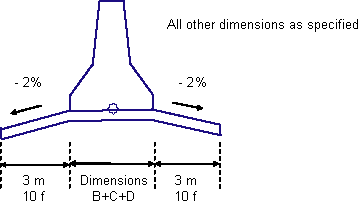
Layout Mode Operation
In layout mode, a median and barrier are drawn with the fixed dimensions as shown in the following diagram. This is the same figure that is drawn in layout mode for the OverlayMedianAsymmetrical subassembly.
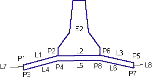
Point, Link, and Shape Codes
The following table lists the point, link, and shape codes for this subassembly that have codes assigned to them. Point, link, or shape codes for this subassembly that do not have codes assigned are not included in this table.
|
Point, Link, or Shape |
Code |
Description |
|---|---|---|
|
P1, P5 |
ETW |
Beginning of median extension at top of overlay |
|
P3, P7 |
ETW_Overlay |
Beginning of median extension at bottom of overlay |
|
All barrier points |
Barrier |
|
|
L1 - L3 |
Top |
Exposed top of overlay layers |
|
L4 - L8 |
Overlay |
|
|
All barrier links |
Barrier |
|
|
S1 |
Overlay |
|
|
S2 |
Barrier |
Coding Diagram