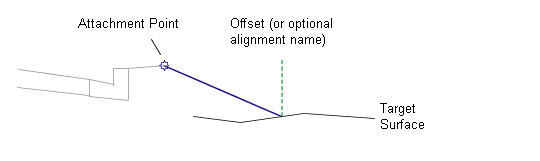
This subassembly is a general purpose utility to extend a link from the attachment point to a given offset on a target surface.
An alignment can be used when building a corridor model to calculate the offset.
Attachment
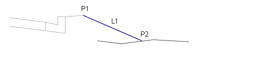
The attachment point is at the beginning of the link.
Input Parameters
Note: All dimensions are in meters or feet unless otherwise noted. All slopes are in run-over-rise form (for example, 4 : 1) unless indicated as a percent slope with a “%” sign.
|
Parameter |
Description |
Type |
Default |
|---|---|---|---|
|
Offset from Baseline |
+/- offset to tie the link into the target surface. Specifying a positive value for the this parameter inserts this subassembly on the right side of a corridor, or controlling baseline. A negative value inserts it on the left side. For more information, see "Inserting Subassemblies on Right and Left Sides of a Corridor" in the Corridors chapter of the Autodesk Civil 3D User's Guide Help. |
Numeric |
0.0 |
|
Point Codes |
A list of surface codes to be assigned to the outside edge of the link |
Comma-separated string |
P2 |
|
Link Codes |
A list of codes to be assigned to the link |
Comma-separated string |
Top, Datum |
|
Omit Link |
This parameter adds or removes the surface link. |
Yes\No |
No |
Target Parameters
This section lists the parameters in this subassembly that can be mapped to one or more target objects, such as a surface, alignment, or profile object in a drawing. For more information, see To Specify Corridor Targets.
|
Parameter |
Description |
Status |
|---|---|---|
|
Offset |
May be used to override the fixed Offset and tie the end-of-link to an offset alignment. The following object types can be used as targets for specifying this offset: alignments, polylines, feature lines, or survey figures. |
Optional |
|
Target Surface |
Name of the surface the link is tying to. The following object types can be used as targets for specifying this surface: surfaces. |
Required |
Output Parameters
|
Parameter |
Description |
Type |
|---|---|---|
|
Begin Offset |
+/- offset of the beginning of the link |
Numeric |
|
Begin Elevation |
Elevation of the beginning of the link |
Numeric |
|
End Offset |
+/- offset of the end of the link |
Numeric |
|
End Elevation |
Elevation of the end of the link |
Numeric |
Behavior
A link is extended to the point on the target surface at the given offset.
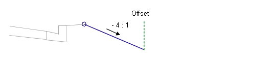
Layout Mode Operation
In layout mode, this subassembly displays the link drawn to the given offset at a -4 : 1 slope. The link terminates with an arrowhead pointing outwards.
Point, Link, and Shape Codes
None.
Coding Diagram