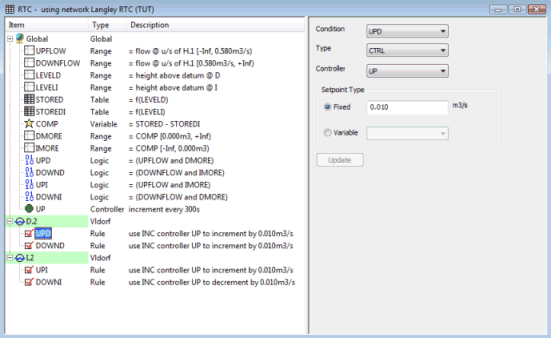
The following example of Real Time Control compares the volume in two tanks and regulates the discharge from these tanks so that a maximum flow is not exceeded.
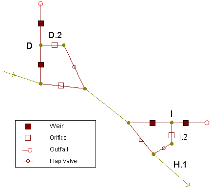
Under this scenario, the flow in conduit H.1 and the levels in tanks D and I are monitored. The volume in Tank D and Tank I is calculated by use of tables, and the difference between the volumes is calculated by use of a Variable. The orifices on the outlet to Tank D and on the outlet to Tank I are controlled incrementally depending on the magnitude of flow in conduit H.1 and which tank contains greater volume:
- If the flow in conduit H.1 is less than or equal to 0.58 m3/s and the volume in Tank D is greater than the volume in Tank I, the orifice at Tank D will open by an increment of 0.01 m3/s
- If the flow in conduit H.1 is greater than 0.58 m3/s and the volume in Tank I is greater than the volume in Tank D, the orifice at Tank D will close by an increment of 0.01 m3/s
- If the flow in conduit H.1 is less than or equal to 0.58 m3/s and the volume in Tank I is greater than the volume in Tank D, the orifice at Tank I will open by an increment of 0.01 m3/s
- If the flow in conduit H.1 is greater than 0.58 m3/s and the volume in Tank D is greater than the volume in Tank I, the orifice at Tank I will close by an increment of 0.01 m3/s
RTC Scenario Summary
Global dependents
|
Component |
Name |
Parameters |
Effect |
|---|---|---|---|
|
RANGE 1 |
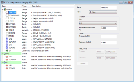
UPFLOW |
Range type: Q - flow Location Link: H.1 Minimum: 0.000 m3/sMaximum: 0.580 m3/s |
TRUE if flow in conduit H.1 is between 0.000 m3/s and 0.580 m3/s |
|
RANGE 2 |
DOWNFLOW |
Range type: Q - flow Location node: H.1 Minimum: 0.580 m3/s Maximum: |
TRUE if flow in conduit H.1 is greater than 0.580 m3/s |
|
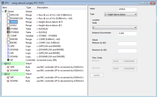
RANGE 3 |
LEVELD |
Range type: Z - Height above datum Location Node: D Minimum: Maximum: |
TRUE if Height above datum at Node D is between - / + infinity |
|
RANGE 4 |
LEVELI |
Range type: Z - Height above datum Location Node: I Minimum: Maximum: |
TRUE if Height above datum at Node I is between - / + infinity |
|
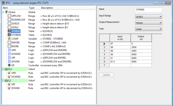
TABLE 1 |
STORED |
Measurement: Volume Input Range: LEVELD Type: Linear Input/Output grid: Height above datum vs Volume |
Relationship between level and volume at Node D |
|
TABLE 2 |
STOREDI |
Measurement: Volume Input Range: LEVELI Type: Linear Input/Output grid: Height above datum vs Volume |
Relationship between level and volume at Node I |
|
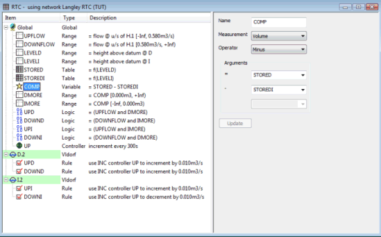
VARIABLE 1 |
COMP |
Measurement: Volume Operator: MINUS Condition 1: STORED Condition 2: STOREDI |
VARIABLE 1 = Volume at Node D - Volume at Node I |
|
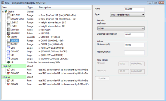
RANGE 5 |
DMORE |
Range type: Variable Location Definition: COMP Minimum: 0.000Maximum: |
TRUE if Volume at Node D is greater than Volume at Node I |
|
RANGE 6 |
IMORE |
Range type: Variable Location Definition: COMP Minimum: Maximum: 0.000 |
TRUE if Volume at Node I is greater than Volume at Node D
|
|
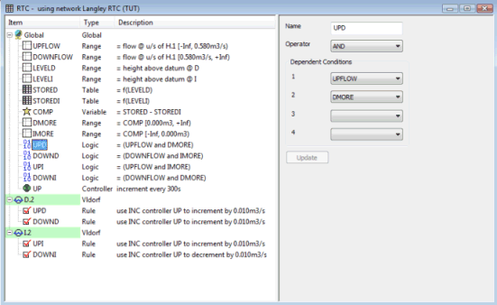
LOGIC 1 |
UPD |
Operator: AND Condition 1: UPFLOW Condition 2: DMORE |
TRUE if flow in conduit H.1 is between 0.000 m3/s and 0.580 m3/s AND Volume at Node D is greater than Volume at Node I |
|
LOGIC 2 |
DOWND |
Operator: AND Condition 1: DOWNFLOW Condition 2: IMORE |
TRUE if flow in conduit H.1 is greater than 0.580 m3/s AND Volume at Node I is greater than Volume at Node D |
|
LOGIC 3 |
UPI |
Operator: AND Condition 1: UPFLOW Condition 2: IMORE |
TRUE if flow in conduit H.1 is between 0.000 m3/s and 0.580 m3/s AND Volume at Node I is greater than Volume at Node D |
|
LOGIC 4 |
DOWNI |
Operator: AND Condition 1: DOWNFLOW Condition 2: DMORE |
TRUE if flow in conduit H.1 is greater than 0.580 m3/s AND Volume at Node D is greater than Volume at Node I |
|
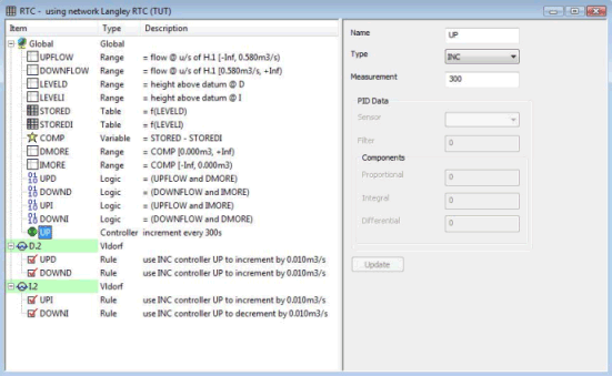
CONTROLLER 1 |
UP |
Type: INC Measurement Interval: 300 |
Measurement interval of orifice increment equals 300 s |
Local Dependents
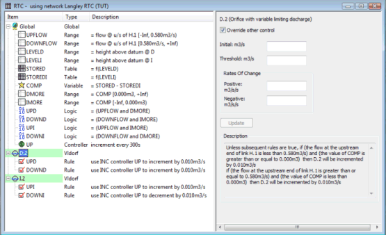
Variable Limiting Discharge Orifice D.2
|
Component |
Name |
Parameters |
Effect |
|---|---|---|---|
|
RULE 1 |
UPD |
Condition: UPDRule type: CTRL Controller: UP Setpoint type: FIXED 0.010 m3/s |
If the flow in conduit H.1 is between 0.000 m3/s and 0.580 m3/s AND Volume at Node D is greater than Volume at Node I, increment the regulator by 0.01 m3/s every 300 s. |
|
RULE 2 |
DOWND |
Condition: DOWNDRule type: CTRL Controlloer: UP Setpoint type: FIXED -0.010m3/s |
If the flow in conduit H.1 is greater than 0.580 m3/s AND Volume at Node I is greater than Volume at Node D, decrement the regulator by 0.01 m3/s every 300 s. |
Variable Limiting Discharge Orifice I.2
|
Component |
Name |
Parameters |
Effect |
|---|---|---|---|
|
RULE 1 |
UPI |
Condition: UPIRule type: CTRL Controller: UP Setpoint type: FIXED 0.010m3/s |
If the flow in conduit H.1 is between 0.000 m3/s and 0.580 m3/s AND Volume at Node I is greater than Volume at Node D, increment the regulator by 0.01 m3/s every 300 s. |
|
RULE 2 |
DOWNI |
Condition: DOWNIRule type: CTRL Controller: UP Setpoint type: FIXED -0.010m3/s |
If the flow in conduit H.1 is greater than 0.580 m3/s AND Volume at Node D is greater than Volume at Node I, decrement the regulator by 0.01 m3/s every 300 s. |
RTC Scenario Steps
- Insert Ranges to measure flow in conduit H.1
- Insert Ranges to measure level at Node D and Node I
- Define relationship between level and volume at Node D and Node I by inserting Tables
- Insert a variable to calculate the difference between volume at Node D and volume at Node I
- Insert Ranges to measure volumes at Node D or Node I
- Insert Logics to determine whether flow in conduit H.1 is less than or greater than 0.580 m3/s and whether the volume at Node D or Node I is greater
- Insert Controller to define time interval for incrementing regulator settings
- Insert Regulators to be controlled
- Insert Rules for each Regulator to determine how the orifice opening is to be regulated