
Description
The CORD1C entry defines a cylindrical coordinate system by referencing three grid point identification numbers.
Format
| 1 | 2 | 3 | 4 | 5 | 6 | 7 | 8 | 9 | 10 |
| CORD1C | CIDA | G1A | G2A | G3A | CIDB | G1B | G2B | G3B |
Example
| CORD1C | 4 | 2 | 44 | 67 |
| Field | Definition | Type | Default |
|---|---|---|---|
| CID | Coordinate system identification number. | Integer > 0 | Required |
| GiA, GiB | Grid point identification numbers. | Integer > 0, G1A ≠ G2A ≠ G3A, G1B ≠ G2B ≠ G3B | Required |
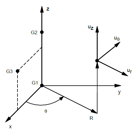
Figure 1: CORD1C definition
Remarks
- Coordinate system identification numbers on all CORD1C, CORD1R, CORD1S, CORD2C, CORD2R, and CORD2S entries must all be unique.
- One or two coordinate systems may be defined on a single entry.
- GiA and GiB must be defined in coordinate whose definition does not involve the coordinate system being defined. The first point is the origin, the second lies on the z-axis, and the third lies in the plane of the azimuth origin. The three grid points GiA (or GiB) must be non-colinear and not coincident.
- Coordinate systems defined using CORD1C, CORD1R, and CORD1S entries cannot be used as reference coordinate systems on CORD2C, CORD2R, and CORD2S entries.
- The location of a grid point (P in the sketch) in this coordinate system is given by (R, θ, Z) where θ is measured in degrees.
- The displacement coordinate directions at P are dependent on the location of P as shown above by (ur, uθ, uz).
- Points on the z-axis will not have their displacement directions defined in this coordinate system since a unique value of θ cannot be defined on the z-axis. For the case of points on the z-axis, the basic rectangular system will be used for displacement output.