
Description
TThe CHEXA entry defines the connections of a six-sided solid element with eight grid points.
Format
| 1 | 2 | 3 | 4 | 5 | 6 | 7 | 8 | 9 | 10 |
| CHEXA | EID | PID | G1 | G2 | G3 | G4 | G5 | G6 | |
Example
| CHEXA | 71 | 4 | 3 | 4 | 5 | 6 | 7 | 8 | |
| 9 | 10 |
| Field | Definition | Type | Default |
|---|---|---|---|
| EID | Element identification number. | Integer > 0 | Required |
| PID | Property identification number of a PSOLID entry. | Integer > 0 | Required |
| Gi | Grid point identification numbers of connection points. | Integer ≥ 0 or blank, all unique | Required |
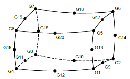
Figure 1: CHEXA element connection
Remarks
- Element identification numbers must be unique with respect to all other element identification numbers.
- Grid points G1 through G4 must be given in consecutive order about one quadrilateral face. Grid points G5 through G8 must be in order in the same direction around the opposite face with G5 opposite G1, G6 opposite G2, etc.
- Components of stress are output in the global coordinate system unless a material coordinate system is defined on the PSOLID entry.
- Figure 1 shows the numbering for both an eight-node and a twenty-node hexahedral element. Autodesk Explicit supports only an eight-node hexahedral element.