
Description
The CBEAM entry defines a beam element.
Format
| 1 | 2 | 3 | 4 | 5 | 6 | 7 | 8 | 9 | 10 |
| CBEAM | EID | PID | GA | GB | G0/X1 | X2 | X3 |
Example
| CBEAM | 10 | 45 | 5 | 21 | 0.5 | 7.0 | -1.3 |
Alternate Format
| CBEAM | EID | PID | GA | GB | G0 |
| Field | Definition | Type | Default |
|---|---|---|---|
| EID | Element identification number. | Integer > 0 | Required |
| PID | Property identification number of a PBEAM entry. | Integer > 0 | Required |
| GA, GB | Grid point identification numbers of connection points. | Integer > 0; GA ≠ GB | Required |
| X1, X2, X3 | Components of vector
 , from GA, in the displacement coordinate system at GA. , from GA, in the displacement coordinate system at GA.
|
Real or blank | |
| G0 | Grid point identification number to optionally supply X1, X2, and X3. Direction of orientation vector is GA to G0. | Integer or blank |
Remarks
- Element identification numbers must be unique with respect to all other element identification numbers.
- The following figure defines beam element geometry:
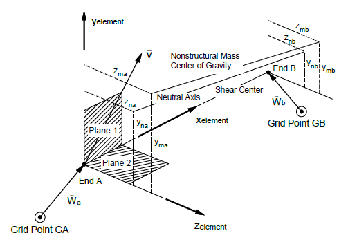
Figure 1: CBEAM element geometry system
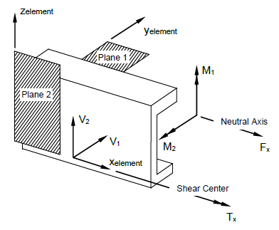
Figure 2: CBEAM internal element forces and moments
- If field 6 is an integer, then G0 is used. If field 6 is blank or real, then X1, X2, X3 is used.
- G0 cannot be located at GA or GB.
- The continuation may be omitted if there are no pin flags or offsets.