
Description
The CTETRA entry defines the connections of a four-sided solid element with four grid points.
Format
| 1 | 2 | 3 | 4 | 5 | 6 | 7 | 8 | 9 | 10 |
| CTETRA | EID | PID | G1 | G2 | G3 | G4 |
Example
| CTETRA | 112 | 2 | 3 | 15 | 14 | 4 |
| Field | Definition | Type | Default |
|---|---|---|---|
| EID | Element identification number. | Integer > 0 | Required |
| PID | Property identification number of a PSOLID entry. | Integer > 0 | Required |
| Gi | Grid point identification numbers of connection points. | Integer ≥ 0 or blank, all unique | Required |
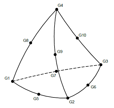
Figure 1: CTETRA element connection
Remarks
- Element identification numbers must be unique with respect to all other element identification numbers.
- The topology of the diagram must be preserved: for example, G1, G2, G3 define a circular face.
- Components of stress are output in the global coordinate system, unless a material coordinate system is defined on the PSOLID option.
- Figure 1 shows the numbering for both a four-node and a ten-node tetrahedral element. Autodesk Explicit supports only a four-node tetrahedral element.