
Description
The MAT8 entry defines the material properties for an orthotropic material for membrane and shell elements and for solid elements. In addition to the material properties, the MAT8 entry also lets the user specify various material failure options. The options on the MAT8 entry are quite extensive, and are outlined in more detail in the Remarks section for the MAT8 entry.
Format
| 1 | 2 | 3 | 4 | 5 | 6 | 7 | 8 | 9 | 10 |
| MAT8 | MID | E1 | E2 | NU12 | G12 | RHO | |||
| A1 | A2 | TREF | Xt | Xc | Yt | Yc | S | ||
| F12 | STRN | CS | EC | GC | ALPHA0 | SB | |||
| EF1 | NUF12 | MSMF | PNPT | PNPC | |||||
| E3 | NU23 | NU31 | E1RSF | E2RSF | G12RSF | G1ZRSF | G2ZRSF |
Example
| MAT8 | 101 | 90.+6 | 1.+7 | 0.3 | 3.+5 | 0.066 | |||
| 29.-6 | 1.1-6 | 175.0 | 1.+3 | 1.1+4 | 4.+2 | 2.+2 | 5.+3 | ||
| 1.0 |
| Field | Definition | Type | Default |
|---|---|---|---|
| MID | Material identification number. Referenced on a PSHELL or PCOMP entry only. | Integer > 0 | Required |
| E1 | Modulus of elasticity in longitudinal direction, also defined as the fiber direction or 1-direction. | Real ≠ 0.0 | Required |
| E2 | Modulus of elasticity in lateral direction, also defined as the matrix direction or 2-direction. | Real ≠ 0.0 | Required |
| NU12 | Poisson's ratio (ε2/ε1 for uniaxial loading in 1-direction). Note that
 21 = ε2/ε1 for uniaxial loading in 2-direction is related to
12, E1, and E2 by the relation
12 E2 =
21 E1. 21 = ε2/ε1 for uniaxial loading in 2-direction is related to
12, E1, and E2 by the relation
12 E2 =
21 E1.
|
Real | Required |
| G12 | In-plane shear modulus. See Remark 2. | Real ≥ 0.0 or blank | 0.0 |
| RHO | Mass density. | Real > 0.0 | 0.0 |
| Ai | Thermal expansion coefficient in i-direction. | Real or blank | 0.0 |
| TREF | Reference temperature for the calculation of thermal loads. See Remarks 4 and 6. | Real or blank | 0.0 |
| Xt, Xc | Allowable stresses or strains in tension and compression, respectively, in the longitudinal direction. Required if composite element failure index is desired. See Remark 3. | Real ≥ 0.0 or blank | Default value for Xc is Xt |
| Yt, Yc | Allowable stresses or strains in tension and compression, respectively, in the lateral direction. These parameters are required if composite element failure index is desired. See Remark 3. | Real ≥ 0.0 or blank | Default value for Yc is Y |
| S | Allowable stress or strain for in-plane shear. See Remark 3. | Real ≥ 0.0 or blank | 0.0 |
| F12 | Interaction term in the tensor polynomial theory of Tsai-Wu. This parameter is required if composite element failure index by Tsai-Wu theory is desired and if value of F12 is different from 0.0. See Remark 7. | Real | 0.0 |
| STRN | For the maximum strain theory only (see STRN in PCOMP entry). Indicates whether Xt, Xc, Yt, Yc, and S are stress or strain allowables. | Real = 1.0 for strain allowable | Blank for stress allowable |
| CS | Honeycomb sandwich core cell size. The CS parameter is required if the material defines the core of a honeycomb sandwich and a dimpling stability index is desired (LAM = HCS on the PCOMP entry). | Real ≥ 0.0 or blank | 0.0 |
| EC | Honeycomb sandwich core Young’s modulus. The EC parameter is used for a stability index analysis. | Real ≥ 0.0 or blank | See Remark 12 |
| GC | Honeycomb sandwich core shear modulus. The GC parameter is used for a stability index analysis. | Real ≥ 0.0 or blank | See Remark 12 |
| ALPHA0 | Fracture angle for uniaxial transverse compression in degrees. The ALPHA0 parameter is used in the NASA LaRC02 failure theory only (see LARC02 in PCOMP entry). | 0.0 < Real < 90.0 | 53.0 |
| SB | Allowable shear stress of the composite laminate bonding material (allowable inter-laminar shear stress). See Remark 9. | Real > 0.0 | PCOMP entry value |
| EF1 | Modulus of elasticity of fiber. The EF1 parameter is used in the Puck PCP failure theory only (see PUCK in PCOMP entry). | Real > 0.0 or blank | E1/0.6 |
| NUF12 | Poisson’s ratio of fiber. The NUF12 parameter is used in the Puck PCP failure theory only (see PUCK in PCOMP entry). | Real ≥ 0.0 or blank | 0.3 |
| MSMF | Mean stress magnification factor. The MSMF parameter is used in the Puck PCP failure theory only (see PUCK in PCOMP entry). See Remark 10. | Real ≥ 0.0 or blank | 1.1 |
| PNPT | Failure-envelope slope parameter for transverse tension. The PNPT parameter is used in the Puck PCP failure theory only (see PUCK in PCOMP entry). See Remark 10. | Real ≥ 0.0 or blank | 0.35 |
| PNPC | Failure-envelope slope parameter for transverse compression. The PNPC parameter is used in the Puck PCP failure theory only (see PUCK in PCOMP entry). See Remark 10. | Real ≥ 0.0 or blank | 0.3 |
| E3 | Modulus of elasticity in thickness direction for shells and membranes. Modulus of elasticity in 3-direction for solids. | Real ≠ 0.0 | |
| NU23 | (ε3/ε2 for uniaxial loading in 2-direction). Note that
32 = ε3/ε2 for uniaxial loading in 3-direction is related to
23, E2, and E3 by the relation
23 E3 =
32 E2.
|
Real ≠ 0.0 | |
| NU31 | (ε1/ε3 for uniaxial loading in 3-direction). Note that
13 = ε1/ε3 for uniaxial loading in 1-direction is related to
31, E1, and E3 by the relation
31 E1 =
13 E3.
|
Real ≠ 0.0 | |
| E1RSF | Longitudinal modulus of elasticity reduction scale factor for nonlinear composite Progressive Ply Failure Analysis (PPFA). See Remark 11. | 0.0 ≤ Real ≤ 1.0 | 0.04 |
| E2RSF | Lateral modulus of elasticity reduction scale factor for nonlinear composite Progressive Ply Failure Analysis (PPFA). See Remark 11. | 0.0 ≤ Real ≤ 1.0 | 0.04 |
| G12RSF | In-plane shear modulus reduction scale factor for nonlinear composite Progressive Ply Failure Analysis (PPFA). See Remark 11. | 0.0 ≤ Real ≤ 1.0 | 0.2 |
| G1ZRSF | Transverse shear modulus reduction factor in 1-Z plane for non-linear composite Progressive Ply Failure Analysis (PPFA). | ||
| G2ZRSF | Transverse shear modulus reduction factor in 2-Z plane for non-linear composite Progressive Ply Failure Analysis (PPFA). |
Remarks
- The material identification number must be unique for all MATi entries.
- The transverse shear moduli G1Z and G2Z are computed automatically from the in-plane shear modulus G12.
- Xt, Yt, and S are required for composite element failure calculations when requested in the FT field of the PCOMP entry. Xc and Yc are also used but not required.
- MAT8 materials may be made temperature dependent by use of the MATT8 entry.
- The mass density, RHO, will be used to automatically compute mass for all structural elements.
- TREF is used only as the reference temperature for the calculation of thermal.
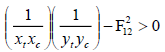
- The interaction term F12 is experimentally determined from test specimens under biaxial loading. The fact that F12 must be determined experimentally, plus a stability constraint on F12, makes the Tsai-Wu theory difficult to use. It is recommended that F12 be set to zero. The stability criterion is:
- The default value for ALPHA0 has been found experimentally and is typical for fiber reinforced polymer laminates. See the Autodesk Inventor Nastran User’s Manual, Reference 5, for additional information.
- The allowable shear stress value SB corresponds to the top surface of the ply. The default value for SB is defined in the SB field of the PCOMP entry and will be used when this field is blank.
- The default values for MSMF, PNPT, and PNPC are for carbon fibers. See the
Autodesk Inventor Nastran User’s Manual, Reference 13, and the table below for additional materials.
Variable Carbon Fiber Glass Fiber MSMF 1.10 1.30 PNPT 0.35 0.30 PNPC 0.30 0.25 - Recommended values for E1RSF, E2RSF, and G12RSF are shown in the table below.
Variable Recommended Value E1RSF 0.04 E2RSF 0.04 G12RSF 0.20