
General Truelight Material Settings
These are the sections common to Truelight materials that are found in the Properties Editor of the Material Editor. For any properties not listed that are specific to a material, see that material in the Truelight Materials Reference section.
Video captions: VRED offers you a wide range of materials. The Phong material is a standard shader. Unicolor paint, Metallic paint, and FlipFlop paint are car finish materials. For metallic surfaces, use Chrome and the Brushed Metal material. For plastic, leather, wood, stone, or anything else, use the Plastic material. For a double clear coat finish or highly reflective non metallic surfaces, use the Reflective Plastic material. With carbon materials, you can simulate interlocked materials with the tire material, Tires. For all transparent material, use the Glass material. Measured materials are presets and very realistic, Shadow materials only show shadows, and the Multipass materials serves a container for other underlaying materials. The Switch material is only used for variants and the Glow only in OpenGL for lighting effects. Sphere Environment and Environment Switch materials are environmental materials, and HDR textures only should be applied to them. Skylight material simulates a physically correct sky. Velvet material and Woven Cloth material are used for textiles and cloth.
Diffuse Texture
Once Use Texture is enabled, an assortment of parameters appear that can be configured:
Use Texture - Loads an image texture for the diffuse color channel. Uses the image as pattern on the surfaces and exposes other diffuse texture settings.
Use Image Sequence - Select when an image sequence is loaded in the Use Texture box. This uses an image sequence as a texture. The image name for the sequence will be generated based on the filename and the image number. Use the Curve Editor to animate the image number. Go to Animation > Timeline. Click play to view the animated image sequence on the material.
Note:For a group of images to be considered an image sequence, there must be at least two images with the same name with an increasing numeric value. The required naming format is name, number, and extension. For example, image000.png image01.png.
Frame Offset - Only available when Use Image Sequence is enabled. Sets an offset to the image number when using an image sequence. An image sequence is loaded from Use Texture.
Inline Image Sequence - Only available when Use Image Sequence is enabled. Inlines the image sequence into the .vpb file. When selected, loaded image sequences are packaged within the .vpb file. If the .vpb is moved to another computer, the image sequence does not need to be moved separately.
Use Alpha - If the image texture has an alpha channel embedded, it is used to make parts of the image texture transparent.
Use Cutout Transparency - Retains the state of a reloaded material and does not reset it to the default. s
Link Texture Settings - Links the texture mapping settings together when multiple texture slots of a material are selected. When changing the Repeat UV of a linked texture, all linked textures are changed at once. When selecting this option for a texture, while other textures of that material are already linked, its texture settings are also set to the already linked settings.
Mapping Type - Sets the mapping type of the texture. There are three modes which can be selected.
UV - For radial and planar brush mapping. UV mapping is always used for Incandescence, Transparency, and Displacement textures.
Planar - For decals. The first two values define the orientation of the plane in 3D, the third value defines the rotation in 2D around the plane normal.
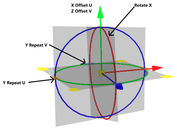
Triplanar - For triplanar brush mapping orientation. Use to apply textures to a geometry with no UVs. There is a blend zone where the projections overlap on the surface. If this does not give the desired result, actual UV coordinates need to be created, and UV must be used as the Mapping Type for the texture in the material.
Repeat Mode UV - Sets how the texture is repeated. There are four modes, which can be set:
Use Texture Size - Only available when Mapping Type is set to UV. Uses the texture size, instead of repeat values. Select to defined texture size in millimeters instead of repeat values for texture mapping. The geometry UV texture coordinates must match the scene units to get real world scaling of the texture. Use Apply World Scale in the UV Editor to calculate the real world scaling of UV coordinates.
Texture Size - Enter the width and height of the texture in millimeters. Only available with the mapping type - UV and Use Texture Size selected or with the mapping type - Triplanar.
Edge Blend - Only available when the Mapping Type is set to Triplanar. Sets the range for overlapping areas of the planar projection.
Uniform Repeat - Only available when the Mapping Type is set to Triplanar. When enabled, the repeat factors of the X/Y/Z axes of the triplanar texture projection are linked.
X Repeat UV - Only available when the Mapping Type is set to Triplanar. Sets the UV repeat factors for the x-axis of the triplanar texture projection.
X Offset UV - Only available when the Mapping Type is set to Triplanar. Moves the position of the texture’s pattern along the x-axis of the triplanar texture projection. The higher the value, the bigger the difference from the original texture pattern.
X Rotate - Only available when the Mapping Type is set to Triplanar. Sets the rotation value for the x-axis texture coordinates of the triplanar texture projection.
Y Repeat UV - Only available when the Mapping Type is set to Triplanar. Sets the UV repeat factors for the y-axis of the triplanar texture projection.
Y Offset UV - Only available when the Mapping Type is set to Triplanar. Moves the position of the texture’s pattern along the y-axis of the triplanar texture projection. The higher the value, the bigger the difference from the original texture pattern.
Y Rotate - Only available when the Mapping Type is set to Triplanar. Sets the rotation value for the y-axis texture coordinates of the triplanar texture projection.
Z Repeat UV - Only available when the Mapping Type is set to Triplanar. Sets the UV repeat factors for the z-axis of the triplanar texture projection.
Z Offset UV - Only available when the Mapping Type is set to Triplanar. Moves the position of the texture’s pattern along the z-axis of the triplanar texture projection. The higher the value, the bigger the difference from the original texture pattern.
Z Rotate - Only available when the Mapping Type is set to Triplanar. Sets the rotation value for the z-axis texture coordinates of the triplanar texture projection.
Repeat UV - Only available when the Mapping Type is set to UV. Sets the number of times the U/V textures is repeated.
Offset UV - Only available when the Mapping Type is set to UV. Moves the position of the texture’s pattern horizontally or vertically. The higher the value, the bigger the difference from the original texture pattern.
Projection Center - Only available when the Mapping Type is set to Planar. Sets the projection center for planar texture projection in object space.
Projection Orientation - Only available when the Mapping Type is set to Planar. Sets the projection orientation for planar texture projection in object space. Offers the possibility to incline the projection plane.
Projection Size - Only available when the Mapping Type is set to Planar. Sets the size of the planar texture projection in object space. The z-coordinate can be used to limit the depth range of the projection.
Keep Aspect Ratio - Only available when the Mapping Type is set to Planar. Sets whether the aspect ratio of the texture should be preserved for the projection or not. If selected, the size, corresponding to the original aspect ratio of the texture, is automatically adjusted.
Consider Face Normal - Only available when Use Texture is enabled and with repeat mode Decal. Sets whether the planar projection should be done on one side of the geometry or both. Use in Decal mode to restrict the projection to one side of the object.
Rotate - Only available when the Mapping Type is set to UV or Planar. For UV, it changes the orientation of the texture. For Planar, it sets the projection plane’s rotation on the X/Y/Z-axis.
Manipulate - Activates and deactivates the interactive texture manipulator in the render window. This function requires a selection in the Scenegraph and a single selection in the Material Editor. Use it to adjust the texture on the selected object. Hold the Shift key and drag on the manipulator to rotate, scale, or translate the texture. Dragging the blue scale control adjusts the depth limit of the texture.
Fit Size - Only available when the Mapping Type is set to Planar. Adjusts the projection size to the size of the selected object in the Scenegraph. This function requires a valid selection in the Scenegraph.
Object Center - Only available when the Mapping Type is set to Planar. Adjusts the projection center to the center of the selected object in the Scenegraph. This function requires a valid selection in the Scenegraph.
Anisotropy - Sets the texture filter quality for the image texture in raytracing. Use the following as a guide:
Input Gamma - Sets the texture image gamma correction. The higher the value, the smoother the texture.
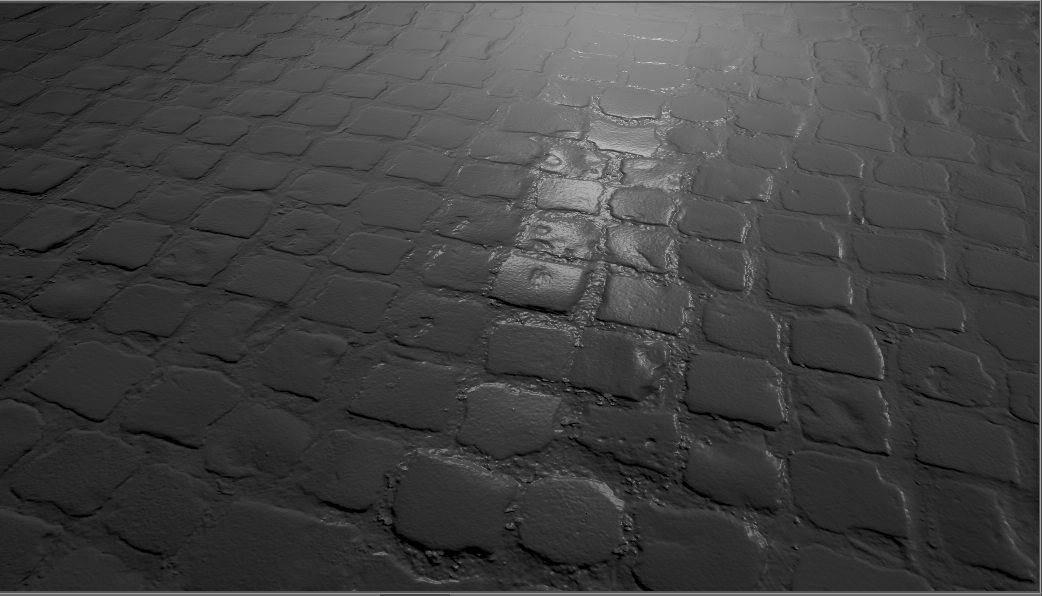
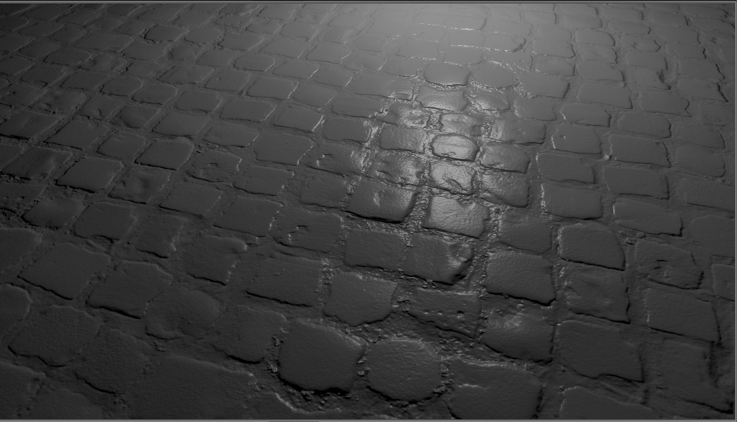
Use Infinite Tiling - Removes repetition artifacts from tiled, seamless textures.
Grid Size - Only available when Use Infinite Tiling is enabled. Sets the sample grid size (m x m) per unit UV-rectangle. A finer grid (larger value) will average out larger scale details and the resulting texture will look more uniform.
Contrast - Only available when Use Infinite Tiling is enabled. Sets the weight of the variance-preserving operation. May need to be lowered to remove excessive color clamping at the cost of blurring.
Max Rotation - Only available when Use Infinite Tiling is enabled. Sets the maximum value texture samples can be rotated.
Hue Weight - Only available when Use Infinite Tiling is enabled. Sets the weight of the random hue shift of each sample.
Saturation Weight - Sets the weight of the random saturation shift of each sample.
Value Weight - Only available when Use Infinite Tiling is enabled. Sets the weight of the random value shift of each sample.
Glossy Texture
Once Use Texture is enabled, an assortment of parameters appear that can be configured:
- Use Texture - Loads an image texture for the glossy color channel. Uses the image as a pattern on the surfaces.
For further information on these common settings, refer to the Diffuse Texture section.
Roughness Texture
As of version 2024, the material roughness control changed to a quadratic roughness with a 0 - 1 range for easier control. This enables VRED to map roughness values from other material libraries. When opening existing scenes, the material appearance will not be changed; however, the value are adjusted to the new 0 - 1 range.
Converting Old Roughness to New
For those who have old materials that need to be converted to this new roughness scale, you can do this either manually or with Python.
Manual Approach
Use a calculator for new conversion values. For example, if you used a VRED roughness value of 2.0 for certain material types, such as leather, you will need to calculate the value for use in the 2024 version.
If a material from an older version with a certain value is imported into 2024, the conversion is done automatically and you will see the new value.
Use these formula to convert an old roughness value to the new and vice versa.
From old to new - To get the new value, divide the old roughness value by 40.0, then take the square root of the result twice.
newRoughness = sqrt(sqrt(oldRoughness / 40.0))
From new to old - To get the old value, multiply the new roughness value by itself four times, and multiply that by 40.0.
oldRoughness = (newRoughness^4) * 40.0
Python Approach
Material roughness can be set with a Python script. VRED 2024 expects the values to use the new range (0 - 1). VRED 2023 and older expect the values use the old range (0 - 40).
Therefore, a script written for an older VRED version (2023.4 and below) might set a specific roughness value.
For example:
leather = vrMaterialService.createMaterial("leather", vrMaterialTypes.Plastic)
leather.setRoughness(2.0) # legacy roughness value for VRED 2023
When using this script in 2024, this value needs to be converted to get the same visual result as in the old VRED version. To do this, the previous formulas can be defined as these two Python functions:
from math import sqrt, pow

def toNewRoughness(oldRoughness):
    return sqrt(sqrt(oldRoughness / 40.0))

def toOldRoughness(newRoughness):
    return pow(newRoughness, 4.0) * 40.0
Therefore, for VRED 2024, this will onvert legacy roughness value to 2024 value:
leather = vrMaterialService.createMaterial("leather", vrMaterialTypes.Plastic)
leather.setRoughness(toNewRoughness(2.0)) # convert legacy roughness value to 2024 value
Use a roughness texture for varying roughness values on the surfaces. If a previously saved roughness texture is selected, the simple roughness slider loses its function. Instead, you can define how the texture values are mapped to roughness values using a minimum and a maximum roughness value. The following parameters can be configured:
- Use Texture - Load an image texture for the roughness channel. Using a grayscale image is recommended, for color images the red channel is used.
- Minimum Roughness - Defines the roughness value to which a texture value of 0 is mapped.
- Maximum Roughness - Defines the roughness value to which a texture value of one is mapped.
For further information on these common settings, refer to the Diffuse Texture section.
Clearcoat
Clearcoat contains options for setting clearcoat attributes to Plastic materials.
Add an additional clearcoat layer and adjust parameters like the thickness, color, and density of the clearcoat. Create, for example, a textured material with a layered clearcoat on top of it. You can also set a clearcoat for multiple Plastic materials at once.
Type - Defines the intensity of a reflection, based on the viewing angle. Its intensity at normal incidence is set by the material's reflectivity. Choose from the following:
Color - Sets the pigment color in the layer.
Refraction Index - Sets the material's refraction index. The index of refraction allows glass-on-glass contact situations. It shows the amount the rays are reflected off the surface versus absorbed (refracted into the surface).
Thickness - Sets the thickness of the clearcoat.
Density - Determines the concentration of particles in the clearcoat, which affects the color of the clearcoat. Use this in combination with Thickness and a non-white color, as white is completely transparent.
Use Orange Peel - Applies a bump structure to the layer. Use the following options to customize this:
- Orange Peel Frequency - Sets the bump structure's noise frequency. The higher the value, the closer together the orange peel bumps.
- Orange Peel Intensity - Sets the bump structure's intensity. The higher the value, the more visible the orange peel and less smooth the clearcoat surface.
Bump Texture
Bump mapping enables the creation of structure to the materials surface. A high value results in more depth structure. If a texture is assigned to the bump map channel, it is used as a pattern figure on surface illustration. If no texture is assigned, a default noise map is used instead; Structure size affects then scale.
Use Structure - Uses a default noise map.
Use Texture - Loads an image texture for the bump channel. Uses the loaded image as a pattern on the surfaces.
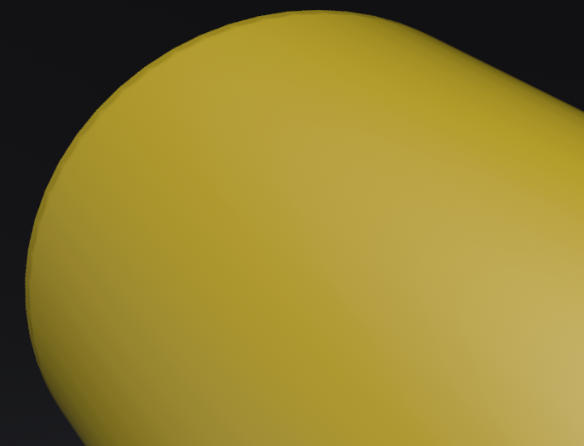
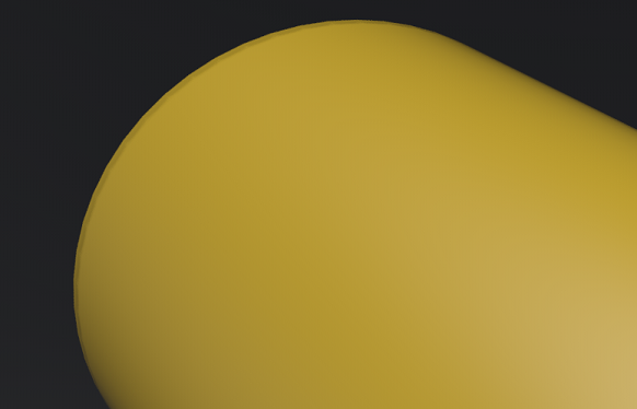
Flip U and Flip V - Switches the orientation of what is stored in the normal map on the axis, ensuring the bump map is uniform with the normals displayed along the U and Y axes. To fix the normal map's tangent vectors orientation, change one of these and see if it corrects the issue. If it doesn't, disable that option and enable the other, or Enable both Flip U and Flip V. These options enable VRED to support different kinds of normal maps, as they provide a solution for aligning the normals.
Incorrect with Flip U disabled Corrected with Flip U enabled Note:When using Flip U or Flip V for a normal map, the Parallax Intensity value should be kept at 0.0, as the height cannot be estimated in this case.
Parallax Intensity - Sets the parallax shift interpretation of the bump image texture.
Bump Intensity - Controls how high the bumps display on a surface. Higher values make the surface appear bumpier. Negative values will invert the bump effect.
Structure Size - Sets the structure size when the procedural bump structure is activated.
Bump Type - Sets the bump type. The bump mapping can be drawn as bump map or as pixel displacement map without self-shadowing.
For further information on these common settings, refer to the Diffuse Texture section.
Displacement Texture
Video captions: Vulkan also comes with a new way of displacement mapping that is faster and features correct self-shadowing through GPU tessellation. This approach significantly improves performance and accuracy. It can still be used in the materials as you know it from older versions of VRED.
Displacement maps are detailed maps, which are interpreted as height information. Floating point displacement maps may encode displacements in both positive and negative directions using real world values. Using displacement maps you can create highly detailed structures from simple geometry by using a plain image. Each point on the geometry is displaced along the interpolated vertex normals using the height information of the map, resulting in a realistic silhouette, producing correct shadows, and reflections. Accuracy is limited by the resolution of the texture image and memory requirements are low. To avoid cracks in the displaced surfaces the vertex normals should be smooth and consistent. Using a higher tessellated base mesh can improve performance.
In OpenGL displacement mapping with transparent materials does not work when Depth Peeling is enabled or when Object Sorting is used in conjunction with the Depth Only Pass.
Hardware Tessellated Displacement Mapping
As of VRED 2026, hardware tessellated displacement mapping is supported for Vulkan to provide significantly better visual quality with minimal impact to performance. This adds fine details to surfaces using the displacement map texture, creating more complex geometry without a high-polygon base mesh. Whenever a material is loaded, uses a displacement texture, and the Displacement Height setting is greater than 0, hardware tessellated displacement mapping is used.
Use Texture - Loads an image texture for the displacement texture. Uses the image as pattern on the surfaces.
Use Image Sequence - Select when an image sequence is loaded in the Use Texture box. This uses an image sequence as a texture. The image name for the sequence will be generated based on the filename and the image number. Use the Curve Editor to animate the image number. Go to Animation > Timeline. Click play to view the animated image sequence on the material.
Note:For a group of images to be considered an image sequence, there must be at least two images with the same name with an increasing numeric value. The required naming format is name, number, and extension. For example, image000.png image01.png.
Frame Offset - Only available when Use Image Sequence is enabled. Sets an offset to the image number when using an image sequence. An image sequence is loaded from Use Texture.
Inline Image Sequence - Only available when Use Image Sequence is enabled. Inlines the image sequence into the .vpb file. When selected, loaded image sequences are packaged within the .vpb file. If the .vpb is moved to another computer, the image sequence does not need to be moved separately.
Link Texture Settings - Links the texture mapping settings together when multiple texture slots of a material are selected. When changing the Repeat UV of a linked texture, all linked textures are changed at once. When selecting this option for a texture, while other textures of that material are already linked, its texture settings are also set to the already linked settings.
Mapping Type - Sets how the texture is mapped onto your geometry. There are three modes which can be selected.
UV - For radial and planar brush mapping. UV mapping is always used for Incandescence, Transparency, and Displacement textures.
Planar - For decals. The first two values define the orientation of the plane in 3D, the third value defines the rotation in 2D around the plane normal.
Triplanar - For triplanar brush mapping orientation. Use to apply textures to a geometry with no UVs. There is a blend zone where the projections overlap on the surface. If this does not give the desired result, actual UV coordinates need to be created, and UV must be used as the Mapping Type for the texture in the material.
Repeat Mode UV - Sets how the texture is repeated, using one of four modes. A different mode can be set for U and V. Enable
 to link the Repeat Mode for U with that of V, so that V always has the same value as U, when active (locked). Choose from:
Repeat - Repeats the texture in all directions.
Mirrored - Repeats and mirrors the texture on the x-and y-axis with every repetition.
Decal - The texture is not repeated.
Clamp - Repeats only the last pixel of the texture is repeated.
Projection Center - Only available when the Mapping Type is set to Planar. Sets the projection center for planar texture projection in object space.
Projection Orientation - Only available when the Mapping Type is set to Planar. Sets the projection orientation for planar texture projection in object space. Offers the possibility to incline the projection plane.
Projection Size - Only available when the Mapping Type is set to Planar. Sets the size of the planar texture projection in object space. The z-coordinate can be used to limit the depth range of the projection.
Keep Aspect Ratio - Only available when the Mapping Type is set to Planar. Sets whether the aspect ratio of the texture should be preserved for the projection or not. If selected, the size, corresponding to the original aspect ratio of the texture, is automatically adjusted.
- Use Texture Size - Only available when Mapping Type is set to UV. Uses the texture size, instead of repeat values. Select to defined texture size in millimeters instead of repeat values for texture mapping. The geometry UV texture coordinates must match the scene units to get real world scaling of the texture. Use Apply World Scale in the UV Editor to calculate the real world scaling of UV coordinates.
Texture Size - Only available when Mapping Type is set to UV and Use Texture Size selected or Triplanar. Enter the width and height of the texture in millimeters.
Offset UV - Only available when the Mapping Type is set to UV. Moves the position of the texture’s pattern horizontally or vertically. The higher the value, the bigger the difference from the original texture pattern.
Rotate - Only available when the Mapping Type is set to UV or Planar. For UV, it changes the orientation of the texture. For Planar, it sets the projection plane’s rotation on the X/Y/Z-axis.
Anisotropy - Sets the texture filter quality for the image texture in raytracing. Use the following as a guide:
A value of 0.0 switches the filtering to normal bilinear filtering without mipmapping.
A value of 1.0 uses normal trilinear filtering with mipmapping.
Values between 1.0 and 16.0 will use anisotropic filtering.
A value of 16.0 is the maximum and provides the highest filtering quality.
Edge Blend - Sets the range for overlapping areas of the planar projection.
Texture Size X, Y - Defines the textures size along the X and Y-axis. Enter the width and height of the texture in millimeters. Only available with the mapping type - UV and Use Texture Size selected or with the mapping type - Triplanar.
Uniform Repeat - Synchronizes the repetition value for all projection axes. If selected, the repeat factors of the x, y, and z axes of the triplanar texture projection are linked.
X Repeat UV - Sets the UV repeat factors for the x-axis of the triplanar texture projection.
X Offset UV - Sets the UV offset for the x-axis of the triplanar texture projection.
X Rotate - Sets the rotation value for the x-axis texture coordinates of the triplanar texture projection. This is a global texture setting that always rotates around the center.
Y Repeat UV - Sets the UV repeat factors for the y-axis of the triplanar texture projection.
Y Offset UV - Sets the UV offset for the y-axis of the triplanar texture projection.
Y Rotate - Sets the rotation value for the y-axis texture coordinates of the triplanar texture projection. This is a global texture setting that always rotates around the center.
Z Repeat UV - Sets the UV repeat factors for the z-axis of the triplanar texture projection.
Z Offset UV - Sets the UV offset for the z-axis of the triplanar texture projection.
Z Rotate - Sets the rotation value for the z-axis texture coordinates of the triplanar texture projection. This is a global texture setting that always rotates around the center.
- Displacement Height - Defines the scaling factor of values for the displacement maps.
- Displacement Offset - Sets an offset for the displacement values to adjust the zero plane. Values less than the offset value will be along the negative normal direction, while values above the offset value will be along the positive normal direction.
- Use Accurate Silhouettes in OpenGL - This feature allows you to calculate the displacement in OpenGL like in raytracing mode. Selecting it may drastically reduce the performance.
For further information on these common settings, refer to the Diffuse Texture section.
- Vulkan Edge Length - Sets the target edge length in scene units for displacement tessellation, which is only used in Vulkan. Low values result in a finer surface structure, but at the price of lower performance. Triangles are tessellated until the edge length is reached. The minimum edge length is limited by the maximum tessellation level provided by the GPU.
- Consider Face Normal - Only available when Use Texture is enabled and with repeat mode Decal. Sets whether the planar projection should be done on one side of the geometry or both. Use in Decal mode to restrict the projection to one side of the object.
- Manipulate - Activates and deactivates the interactive texture manipulator in the render window. This function requires a selection in the Scenegraph and a single selection in the Material Editor. Use it to adjust the texture on the selected object. Hold the Shift key and drag on the manipulator to rotate, scale, or translate the texture. Dragging the blue scale control adjusts the depth limit of the texture.
- Fit Size - Only available when the Mapping Type is set to Planar. Adjusts the projection size to the size of the selected object in the Scenegraph. This function requires a valid selection in the Scenegraph.
- Object Center - Only available when the Mapping Type is set to Planar. Adjusts the projection center to the center of the selected object in the Scenegraph. This function requires a valid selection in the Scenegraph.
- Use Infinite Tiling - Removes repetition artifacts from tiled, seamless textures.
- Grid Size - Only available when Use Infinite Tiling is enabled. Sets the sample grid size (m x m) per unit UV-rectangle. A finer grid (larger value) will average out larger scale details and the resulting texture will look more uniform.
- Max Rotation - Only available when Use Infinite Tiling is enabled. Sets the maximum value texture samples can be rotated.
Incandescence
The effect of the object itself giving off light. Incandescence is useful in various cases where an object needs to be lit without the use of a full light object in the scene. Settings are available for the object to affect the lighting of only itself or the surrounding scene.
- Intensity - Sets the strength of the incandenscence (Ranging from 0-1000).
- Color - Sets the color of the incandescence light rays.
Bake as Separate Illumination - This option is only used during texture baking when "Enable Separate Illumination" is enabled in the Bake Light and Shadows module. If enabled, light emitted from geometries with this material will be baked into the separate illumination lightmap. If disabled, it will be baked into the base lightmap.
With this, you can switch, rotate, or change an environment and/or its exposure without affecting things like a door panel's ambient light, since it was baked into a separate lightmap. Use scripts to change the intensity of separate baked lightmaps to turn a door panel's ambient light on and off and the color in real-time.
Note:For older scene (not created in 2022.1), no baked light will appear on the Shadow material.
- Evaluate Ray Lights (Raytracing Only) - Only available in Raytracing mode. Enables evaluation of ray lights on the surface. This is used to be able to look into a ray file light and to make it visible in reflections and refractions. The origins of the rays should be on the surface to be evaluated.
- Use as Light Source (Raytracing Only) - Only available in Raytracing mode. Uses the material as a light source for other materials in the scene while raytracing.
- Illuminate Shadow Material - Only available when Evaluate Ray Lights (Raytracing Only) or Use as Light Source (Raytracing Only) is enabled. Allows the incandescence light to illuminate shadow materials. Set the Reflection Mode of the shadow material to Diffuse, Glossy, or Diffuse + Glossy.
- Cast Shadow on Shadow Material - Only available when Evaluate Ray Lights (Raytracing Only) or Use as Light Source (Raytracing Only) is enabled. Allows other objects to cast shadows on the shadow material due to the material's incandescence illumination.
- Material Shadow Intensity - Only available when Evaluate Ray Lights (Raytracing Only) or Use as Light Source (Raytracing Only) is enabled. Sets the shadow intensity cast on BRDF-based materials by the geometry light.
- Ground Shadow Intensity - Only available when Evaluate Ray Lights (Raytracing Only) or Use as Light Source (Raytracing Only) is enabled. Sets the shadow intensity of the generated light soources on the shadow material.
- Importance Multiplier - Only available when Evaluate Ray Lights (Raytracing Only) or Use as Light Source (Raytracing Only) is enabled. If Use As Light Source is selected, objects with this material function as geometric light sources. A value higher than one increases the probability that the light source emits photons at the photon mapping. This is useful for dark light sources in an interior if incident light comes from outside Environments.
- Interactive/Still Frame Quality - Only available when Evaluate Ray Lights (Raytracing Only) or Use as Light Source (Raytracing Only) is enabled. Controls the illumination and sets the light sampling quality during interactive/still frame rendering.
For further information on these common settings, refer to the Diffuse Texture section.
Transparency
Define the shader’s opacity.
See Through - Renders the material transparent.
As of 2025.3, VRED supports material transparency when importing JT files. When importing a JT file, the transparency parameter in the JT material is mapped to HSV color parameter in the See Through option. This change eliminates extra post-processing that was required, as a result of the missing transparency information.
- Use Texture - Enables the use of a texture to control the intensity of the effect according to the transparency values. When selected, additional options appear. See the Diffuse Texture section for information on these options.
Use Cutout Transparency - Only available when Use Texture is enabled. - Retains the state of a reloaded material and does not reset it to the default. Use for objects with parts that are fully opaque and fully transparent, like grills or grass.
Tip:this is often used in conjunction with a layered material.
For further information on these common settings, refer to the Diffuse Texture section.
Subsurface Scattering
Subsurface Scattering Video Captions: In VRED 2021, we have now improved the way we are calculating subsurface scattering. The new algorithm is a brute force volume-scattering algorithm. This is very helpful for materials like translucent plastics, marble, skin, or leaves. In the material setting of a plastic, you can enable the volume scattering, and choose between two types. Below, you will find all necessary settings for achieving different subsurface scattering looks. This new feature gives you the possibility to get a more realistic and physically correct look and behavior of your materials. Thanks for watching the video.
Translucency and subsurface scattering are two different methods for calculating light passing through the back of an object into the observer's eye. While translucency requires far less calculation power, subsurface scattering offers more possibilities and greater flexibility.
Subsurface scattering simulates the effect of light entering an object and scattering beneath its surface. Use this for the realistic rendering of materials, such as translucent plastic, marble, skin, leaves, wax, and milk. With these types of materials, not all light reflects from a surface. Some of it will penetrate below the surface of an illuminated object. There, it will be absorbed by the material and scattered internally. Some of this scattered light will make its way back out of the surface and become visible to the camera.
Geometries using subsurface scattering must be solids and they must not contain or intersect with other geometries.
Mode - Loads the selected image as a texture when working with an object’s translucency. It provides a more realistic and physically correct look and behavior. Multiple Scattering works best for solid objects.
There are two modes when operating with translucency, depending on what objects to project:
None - Disables subsurface scattering.
Thin Walled Translucency - Only color and roughness values can be set. Simulates translucency on single-sided objects, so the subsurface is rendered as a translucent object being lit from behind. Use for thin-sided objects, such as bubbles, thin cloth, thin leaves, lamp shades, or sheet of paper lit from behind.
It requires more calculation time than the solid translucency mode, but when in doubt, use this mode.
Volume Scattering - Simulates light scattered by a thin, uniform atmosphere. This produces full random walk volume scattering, which is shafts of light and volumetric shadows cast from geometric objects. Use it for fog or smoke. It works with point, spot, area, rectangular, spherical, disc, and directional lights, but not with ray.
Weight - Only available for Volume Scattering. Sets the influence on the blending of the diffuse and subsurface scattering (SSS). A value of 1 uses full SSS and 0 uses none. Note that the glossy or specular term is not affected by this weight; however, the index of refraction controls the reflectivity of the glossy or specular term in order to stay physically plausible.
Color - Only available when a Subsurface Scattering mode is selected. Determines the subsurface scattering effect. A combination of the color, the radius, and the attenuation will be used to determine coefficients for scattering and absorption used in the algorithm.
Radius - Only available for Volume Scattering. Sets the maximum approximated distance light can scatter below the surface, also known as “mean free path” (MFP). This parameter affects the average distance that light might propagate below the surface before scattering back out. This effect on the distance can be specified for each color component separately. The higher the value, the smoother the appearance of the subsurface scattering (SSS). The lower the value, the opaquer the look. Increasing the radius can radically change a material’s appearance. Since SSS is scale dependent, adjust Attenuation as per the size of your model.
Roughness - Only available for Thin Walled Translucency. Sets the surface roughness for thin walled translucency.
Use Texture - Loads an image texture for the subsurface scattering channel. Uses the image as pattern on the surfaces and exposes other subsurface scattering settings.
Use Image Sequence - Select when an image sequence is loaded in the Use Texture box. This uses an image sequence as a texture. The image name for the sequence will be generated based on the filename and the image number. Use the Curve Editor to animate the image number. Go to Animation > Timeline. Click play to view the animated image sequence on the material.
Note:For a group of images to be considered an image sequence, there must be at least two images with the same name with an increasing numeric value. The required naming format is name, number, and extension. For example, image000.png image01.png.
Link Texture Settings - Links the texture mapping settings together when multiple texture slots of a material are selected. When changing the Repeat UV of a linked texture, all linked textures are changed at once. When selecting this option for a texture, while other textures of that material are already linked, its texture settings are also set to the already linked settings.
Mapping Type - Sets the mapping type of the texture. There are three modes which can be selected.
UV - For radial and planar brush mapping. UV mapping is always used for Incandescence, Transparency, and Displacement textures.
Planar - For decals. The first two values define the orientation of the plane in 3D, the third value defines the rotation in 2D around the plane normal.
Triplanar - For triplanar brush mapping orientation. Use to apply textures to a geometry with no UVs. There is a blend zone where the projections overlap on the surface. If this does not give the desired result, actual UV coordinates need to be created, and UV must be used as the Mapping Type for the texture in the material.
Repeat Mode UV - Sets how the texture is repeated. There are four modes, which can be set:
Repeat - Repeats the texture in all directions.
Mirrored - Repeats and mirrors the texture on the x-and y-axis with every repetition.
Decal - The texture is not repeated.
Clamp - Repeats only the last pixel of the texture is repeated.
Use Texture Size - Only available when Mapping Type is set to UV. Uses the texture size, instead of repeat values. Select to defined texture size in millimeters instead of repeat values for texture mapping. The geometry UV texture coordinates must match the scene units to get real world scaling of the texture. Use Apply World Scale in the UV Editor to calculate the real world scaling of UV coordinates.
Texture Size - Only available with the mapping type - UV and Use Texture Size selected or with the mapping type - Triplanar. Enter the width and height of the texture in millimeters.
Offset UV - Only available when the Mapping Type is set to UV. Moves the position of the texture’s pattern horizontally or vertically. The higher the value, the bigger the difference from the original texture pattern.
Rotate - Only available when the Mapping Type is set to UV or Planar. For UV, it changes the orientation of the texture. For Planar, it sets the projection plane’s rotation on the X/Y/Z-axis.
Anisotropy - Sets the texture filter quality for the image texture in raytracing. Use the following as a guide:
A value of 0.0 switches the filtering to normal bilinear filtering without mipmapping.
A value of 1.0 uses normal trilinear filtering with mipmapping.
Values between 1.0 and 16.0 will use anisotropic filtering.
A value of 16.0 is the maximum and provides the highest filtering quality.
Use Infinite Tiling - Removes repetition artifacts from tiled, seamless textures.
Grid Size - Only available when Use Infinite Tiling is enabled. Sets the sample grid size (m x m) per unit UV-rectangle. A finer grid (larger value) will average out larger scale details and the resulting texture will look more uniform.
Max Rotation - Only available when Use Infinite Tiling is enabled. Sets the maximum value texture samples can be rotated.
Attenuation - Only available for Volume Scattering. Sets how deep light is likely to penetrate a surface before reflecting back out. It calculates a scaling factor that multiplies the Radius Color. The distance that the light travels inside the medium is dependent on the attenuation value. The higher the value, the more light absorbed inside/by the medium.
The scaling factor is calculated as
radius scale = ((1.0 / (Attenuation*Attenuation)) - 1.0)A value of 0.0 will, therefore, make the material completely transparent, while a value of 1.0 will make it completely solid.
Asymmetry - Only available for Volume Scattering. Sets the directional characteristic of incoming light and its weighted behavior, using the Henyey-Greenstein Anisotropy coefficient between -1 (full back-scatter) and 1 (full forward-scatter). The value, minus 1, defines the light as completely distributed to the adverted side along the incoming light path. The default, a value of 0, describes a homogeneous distribution of light inside an isotropic medium, which scatters the light evenly in all directions, giving a uniform effect. Positive values bias the scattering effect forwards, in the direction of the light, while negative values bias the scattering backward, toward the light.
Max Scatter Depth - Only available for Volume Scattering. Sets the maximum number of scatter events that can happen before a ray leaves the volume and hit the surface.
Select Medium - Only available for Volume Scattering. Offers a large selection of common index refraction values, based on materials existing in reality. The selected medium affects the Index of Refraction, automatically.
Index of Refraction - Only available for Volume Scattering. Defines the optical density or index of refraction of the material, and therefore, the way light enters and leaves the volume, as well as the reflectivity of the specular or glossy component of the material.
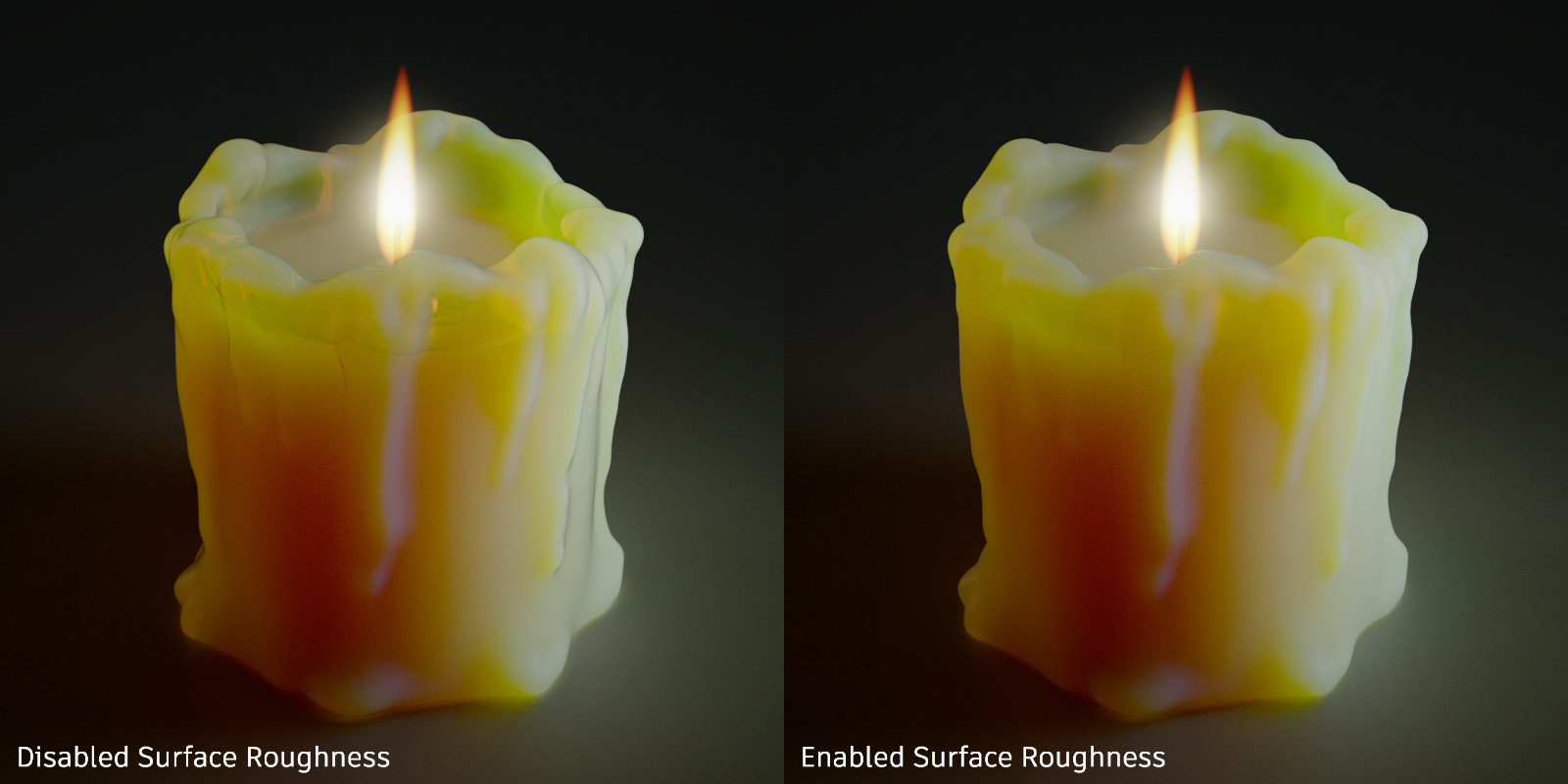
Use Surface Roughness - Enables the roughness of a material to affect the way light scatters into or out of a volume. This effect is typically observed with organic materials, such as beeswax, skin, or leaves.
For further information on these common settings, refer to the Diffuse Texture section.
Raytracing
These settings take effect in Raytracing rendering mode only.
- Material ID - Sets the ID of the material in a range of [0, 31].
- Use Local Environment - Uses the local environment for raytracing.
- Ignore Photon Map - Uses path tracing on this material even when photon mapping is turned on.
- Override Illumination Mode - Overrides the global illumination modes for interactive or still frame rendering.
Interactive - Only available when Override Illumination Mode is enableed. Overrides the global illumination modes for interactive rendering.
Still Frame - Only available when Override Illumination Mode is enableed. Overrides the global illumination modes for still frame rendering.
Select one of the following:
Precomputed - This mode does not compute direct reflection, nor does it compute refraction or any other sophisticated visual effect. This mode is comparable to VRED rasterization rendering mode.
Precomputed + Reflections - This mode uses precomputed Ambient Occlusion and indirect illumination for rendering and calculates specular reflections, refractions, and correct shadows from light sources.
Precomputed + Shadows - This mode uses precomputed image-based lighting and indirect illumination but doesn’t use precomputed Ambient Occlusion values. Instead it calculates shadows based on the active environment.
Precomputed + IBL - This mode uses precomputed indirect illumination and samples the environment.
Full Global Illumination - The Full Global Illumination Mode doesn’t use any precomputed values but accurately samples everything in a physically based approach. Other features like Photon Mapping require the render mode to be set to Full Global Illumination.
Override IBL Sampling Quality - If selected, the setting overrides the global IBL Sampling quality for sampling the environment map.
Interactive/Still Frame - Only available when Override IBL Sampling Quality is enableed. Sets the IBL sampling quality during interactive/still-frame rendering.
Override Reflection/Refraction Sampling Quality - Overrides the global sampling quality for reflections and refractions for rendering.
Interactive/Still Frame - Only available when Override IBL Sampling Quality is enableed. Overrides the global sampling quality for reflections and refractions for interactive/still frame rendering.
Override Trace Depth - Overrides the global trace depth modes during rendering.
Interactive/Still Frame - Only available when Override IBL Sampling Quality is enableed. Overrides the global trace depth modes during interactive/still frame rendering.
Rounded Edges
This feature is only available in Raytracing mode.
Have you wanted an effect that simulates a smooth edge between adjoining faces? Set the Rounded Edges parameters to do just that. Use them when presenting a prototype model. By setting these, you can convey the look and feel of a properly modeled object, without the extra upfront effort. If the design is approved, then the additional modeling effort can begin.
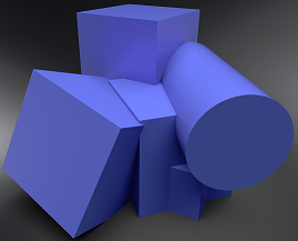 Not using Rounded Edges
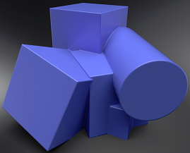 Using Rounded Edges
Mode - Sets whether edges should appear rounded in raytracing or not. There are four options:
Off - No edge rounding; therefore, all other parameters are disabled.
Same Geometry - Only rounds edges belonging to the same geometry or shell.
Same Material - Only rounds edges between objects with the same material.
Same Group - Only rounds edges between materials with the same group ID. This can be useful for an eyeball and lid, where there are different materials, yet you want a smooth edge between them to catch the highlight.
- Group - Only available Mode is set to Same Group. Sets the groupid for the rounded edge effect. Only objects with the same group id will be considered for rounded edge smoothing. Clicking the left arrow in the field provides the option, All Geometries, which applies rounded edges to all geometry in the group.
Type - Sets the type of edges rounded. By default convex and concave edges will be rounded. Choosing either convex or concave edges only can improve the performance of the rendering. There are three options:
Convex & Concave - Both convex and concave edges are rounded.
Convex Only - Only convex edges are rounded. This speeds up calculations when there are only convex edges.
Concave Only - Only concave edges are rounded. This speeds up calculations when there are only concave edges.
- Radius - Sets the radius for rounded edges in world space.
- Chamfer - Gives the edge a more chamfered appearance, instead of a perfectly round shape.
Angle Limit - Limits the rounding effect to edges with an angle above the given limit. If the angle between the current shading normal aand the shading normal of the adjoining edge is smaller than the limit no smoothing will be applied.
Use this limit to avoid the effect on edges already smoothed by the interpolation of the shading normals.
Quality - Sets the number of rays used to evaluate the nearest edges. Each quality level represents a multiple of 4 samples for estimating either convex or concave edges.
A quality level of 1 will trace 4 rays to estimate convex edges and 4 rays to estimate concave edges. At quality level 1, the effect is also only evaluated for non-distributed rays, not rays originating from diffuse or glossy brdfs. At higher quality levels, the effect is evaluated for one additional bounce.
Common
The common settings define material settings that are present in all BRDF materials.
Projection Space - Sets the texture coordinate system to be used for texture projections, to the Common section of the Material Editor.
Video Player is loading.
Video captions: VRED now supports World Space texture transforms for materials. For example, a different scaling on a separate parent node, can influence the flake size of the car paint. And to fix this, you needed to flush the transformation, which can be an issue, when re-importing parts multiple times. But now you have the option to set the projection space from object to world space, and you don’t need to flush the transformation anymore. This also improves interoperability and consistency with Alias.
Choose from:
Object Space - Calculates triplanar, planar, or procedural texture projections in object space, ensuring textures transform with the object and maintain their relative placement regardless of the object's position in the scene. Use this to rotate an object and have the texture rotate with it.
World Space - Uses the world space for calculating triplanar, planar, or procedural texture projections, where the projected textures or structures remain independent of object transformations unless the world space texture transform is frozen. Use this for a ground texture where the texture needs to be aligned to the world space. Be aware, this could cause a distortion on the surface, depending on its rotation.
- Occlusion Color - Sets the color of the pre-calculated ambient occlusion or environment shadows.
- Occlusion Intensity - Controls the intensity of shadowed areas.
- Compress Textures - Only supported in OpenGL mode. Compresses all used textures to save disk space and helps to reduce memory requirements in large scenes.
- Sort Key - Only supported in OpenGL mode. Changes the order in which transparent materials are rendered in OpenGL. Transparent surfaces with the same sort key are sorted back to front.
Line Tube Radius - Controls the radius of tubes used to render lines with raytracing or the Vulkan renderer (given in object space). Apply any material to line geometry and set the line thickness.
Video Player is loading.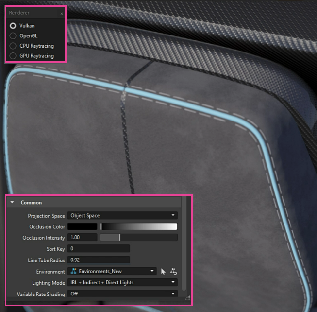
Environment - Use context menu to set the HDR image used for reflections on this material. The HDR image of the assigned environment is used for diffuse, glossy, and specular reflections on this material in rasterization rendering. Different materials can have different environments assigned to get different lighting effects. In Raytracing, the handling of the environment depends on the active illumination mode.
Sets the HDR image used for the light source. The HDR image of the assigned environment is used for diffuse, glossy, and specular reflections on this material in rasterization rendering. Different materials can have different environments assigned to get different lighting effects.
In Raytracing, the handling of the environment depends on the active illumination mode.
Lighting Mode - Defines the light model to be used for the shader. There are five different lighting models.
IBL + Indirect + Direct Lights - The shader is affected by the HDR-Image, by the pre-calculated or interactive Global Illumination rendering and by the direct light sources placed in the scene.
IBL + Indirect - The shader is affected by the HDR-Image and by the pre-calculated or interactive Global Illumination rendering.
IBL + Direct Lights - The shader is affected by the HDR-Image and the direct light sources placed in the scene.
IBL - Only the HDR-Image affects the shader.
Direct Lights - Only direct light sources placed in the scene affect the shader.
Variable Rate Shading - This is an OpenGL-specific rendering feature.
Set the shading rate per material, such as coarse 2x2 or supersampling 4x. Use variable rate shading to vary the amount of processing power required for different parts of an image. The pixels where the user is looking are rendered at a higher resolution than anything in their periphery, saving processer power. Variable rate shading also provides a smoother VR experiences.
For materials with fine patterns that are prone to the moiré effect, such as carbon or HMI textures with thin lines that appear aliased, use a supersampling shading rate. If you are looking for better performance, use the coarse shading rates, which has no other purpose than that. Both of these can be used in VR and desktop mode.
E.g., all materials are rendered "normally" with the native shading rate (1 sample per pixel), but the carbon material should be rendered with supersampling (4 samples per pixel).
When using foveated rendering at the same time, the material is always rendered with its custom shading rate. For example, the carbon material is rendered with 4 samples on the whole screen, as well as in the periphery of the foveated area.
Off - Disables content adaptive variable rate shading.
1 Sample - Native pixel sampling. Enables variable rate shading for normal pixel shading, but no visual difference to VRS off.
1 Sample per 4 pixel - Enables variable rate shading for coarse pixel shading with 1 sample per 4 pixel.
1 Sample per 16 pixel - Enables variable rate shading for coarse pixel shading with 1 sample per 16 pixel.
2 Samples - Enables variable rate shading for supersampled pixel shading with 2 samples per pixel.
Important:This mode requires Realtime-Antialiasing to be enabled with a minimum corresponding multisampling sample amount.
4 Samples - Enables variable rate shading for supersampled pixel shading with 4 samples per pixel.
Important:This mode requires Realtime-Antialiasing to be enabled with a minimum corresponding multisampling sample amount.
8 Samples - Enables variable rate shading for supersampled pixel shading with 8 samples per pixel.
Important:This mode requires Realtime-Antialiasing to be enabled with a minimum corresponding multisampling sample amount.