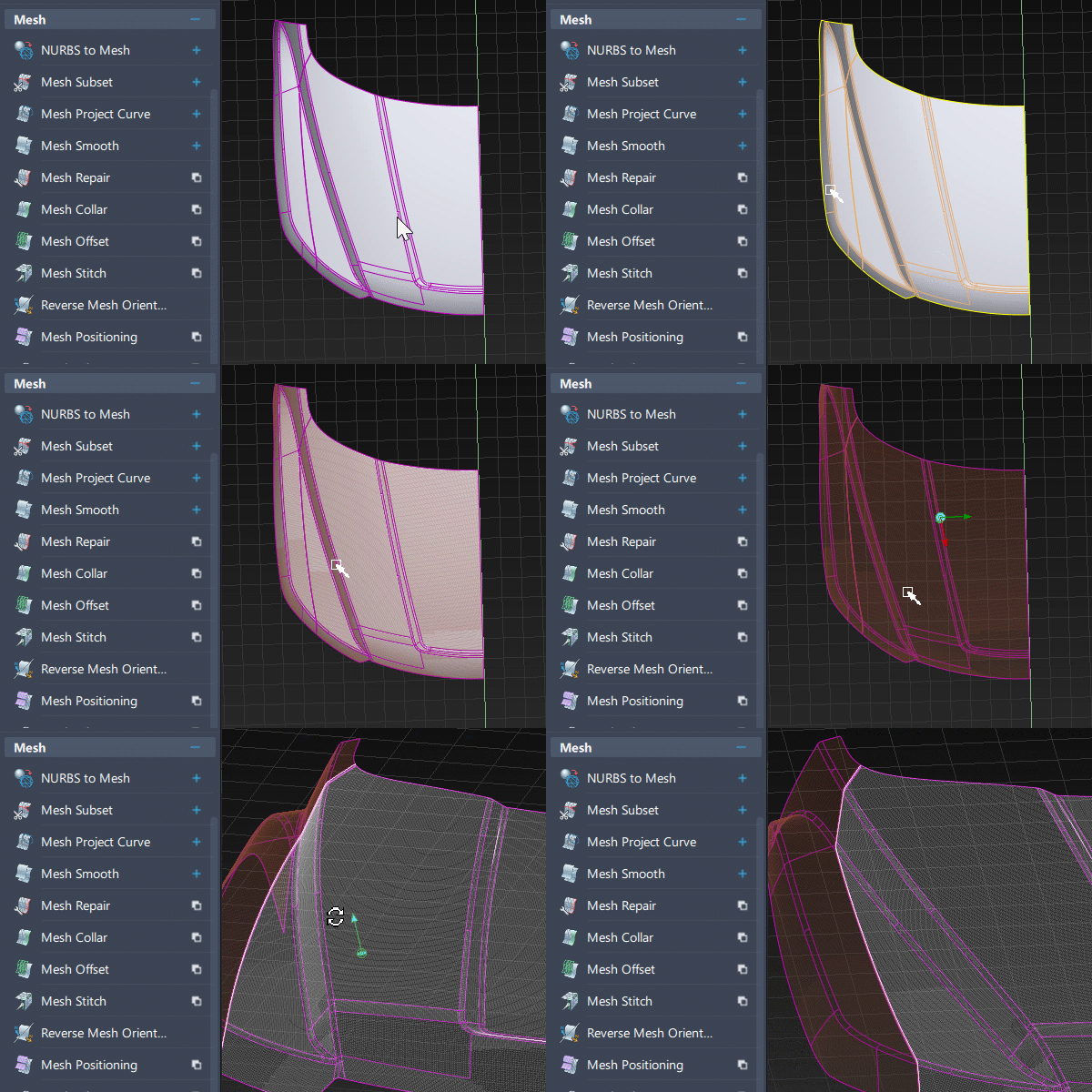
 NURBS to Mesh
Converts NURBS surfaces to mesh objects. A mesh is a large polygonal object resulting from scanning and digitizing physical objects to create data models in Alias.
Meshes can contain several million triangles and, because of their internal representation, are an efficient way to store large and detailed data models representing real objects.

Meshes can be separated into pieces that can be shaded independently, deleted, or toggled invisible. However, you cannot select and manipulate individual vertices or triangles in meshes. You can use either Hardware Shade or any of the Diagnostic Shading modes from the Diagnostic Shade window to shade a mesh.
You can save meshes to .wire and .obj files or export them to the .stl file format.
Access this tool from the Mesh tool palette:

NURBS to Mesh Tool Options
Use existing tessellation
If this option is ON and the surface has already been tessellated through WindowDisplay > Hardware Shade ![]() or the Diagnostic Shading panel, that tessellation is used, and does not need to be recalculated. Otherwise the tessellation parameters from the Control Panel are used.
or the Diagnostic Shading panel, that tessellation is used, and does not need to be recalculated. Otherwise the tessellation parameters from the Control Panel are used.
If this option is OFF, the tessellation is recalculated based on the values of the following options.
Tessellator
Fast – Tessellates more quickly and less accurately.
Accurate – Tessellates more accurately and more slowly.
The same option is used in the option window of WindowDisplay > Hardware Shade ![]() .
.
Tolerance
Controls how accurately surfaces are tessellated. The slider range is 0.0001 to 1.0. The default value is 0.1.
The same tolerance value is found in the option window of WindowDisplay > Hardware Shade ![]() .
.
Limit edge length
This option only appears if Tessellator is set to Accurate.
If checked, a Max edge length slider appears, to control how large the triangles can get. If unchecked, there is no limit on the size of the triangles.
Max edge length
Specifies the maximum length of any triangle edge (in current linear units).
Tessellate shells
When checked, this option ensures that shells are converted to meshes that contain no gaps or T-edges, hence producing better results for visualization and conversion to STL format.
Merge Type
This option is only available when Tessellate shells is turned on.
Modeling – Coincident vertices are merged and normals are averaged at the merged vertices. This is the recommended option for modeling purposes. It also reduces file size.
Visualize – Normals are preserved. Hence, coincident vertices are only merged if they also have coincident normals. This is the default, as it is the recommended option to use on shells that have been converted to meshes for visualization purposes.
NURBS to Mesh workflow
Create meshes from NURBS surfaces or shells
Select all the NURBS surfaces and shells for which you want to create meshes.
Select the Nurbs to Mesh tool
 .
.New mesh objects are created by tessellating the surfaces and shells you selected.
Note: If you want to control how the objects are tessellated, use the parameters within the option window.
