
This item appears in the model tree immediately below Elements.
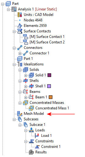
The total number of Nodes and Elements are displayed in the browser, after the Units node.
Right-click on Mesh Model. The following options are available from the context menu:
- Edit
- Switch To

- Global Mesh
- Mesh Table
- Generate Mesh
- Delete Mesh
- Display Mesh
- Hide Mesh
- Check Quality for Mesh
- Add Mesh Control
Follow the links at the bottom of this page to learn more about each of the above commands.
General Meshing Capabilities
The following list summarizes the Inventor Nastran meshing capabilities, particularly in regard to mixing element types:
- Intersecting sketch segments are automatically divided at intersections to create coincident nodes. This feature connects beam element parts to each other without you having to manually divide and intersect the sketch members.
- Shells and beams can be combined. Where a sketch line is coincident with a CAD surface edge, the meshes are automatically matched. (* see note)
- Shells and solids can be combined directly (matching coincident mesh).
- Solids and beams can be combined directly (matching coincident mesh). Where a sketch line is coincident with a CAD surface edge, the meshes are automatically matched. (* see note)
* Note: Connections to beam elements do not occur at the midside nodes of solid or shell elements. While quadratic variants with midside nodes are available for solid and shell elements, there are no quadratic beam elements.
 For more information about combining element types, see the
Finite Elements in
Autodesk Inventor Nastran topic.
For more information about combining element types, see the
Finite Elements in
Autodesk Inventor Nastran topic.