This topic includes information on why an issue might occur, approaches to resolving issues, and links to information that can assist in working through an issue.
- When a link takes you to a topic page and you want to find any mention of the word error, use CTRL + F (standard browser Find command) and enter error in the search field. This finds all occurrences of the word error in the topic page.
- Review related subtopics as you may find the answer there.
This list of links is designed to help locate information that may be useful in resolving an error.
- Analysis and Simulation
- Application Options and Document Settings
- Assembly Errors
- Best Practices for Fixing Errors
- Design Doctor
- Drawings
- Error Reporting
- Edit RVT errors
- File Open Errors
- File Save Errors
- iLogic
- Imported Data Errors
- Installation
- Mold Design
- Part Errors - related to feature creation and edit, material libraries, and Tolerance messages
- Project File
- Sheet Metal
- Routed Systems
- Sketch Doctor
- Sketches and Sketch Dimensions
- Task Scheduler
Analysis and Simulation
Application Options and Document Settings
Error: Cannot read texture image <path>
The specified *.dds file is not found in the specified folder mapping to the path. Locate the .dds files and put them in the folder or specify the path and folder where you find the .dds files. They may have been manually moved after install.
For information about the modeling environment application option, see: Colors Tab Reference.
For information about the document setting, see: Drawing Tab Reference.
Assembly errors
- About Interference Between Components
- Design Accelerator Doctor dialog box
- Synchronous Belt Strength Check - relates to belt design and speed
Assembly Features
If you delete a component that contains a dependent assembly feature, the assembly feature “goes sick,” and the dependent assembly sketches remain in the browser. In the Design Doctor, you can replace the deleted component with a new component using the Redefine command.
Assembly Relationships
Frame Generator
Content Center
Best Practices for Fixing Errors
When fixing several errors, work from the top of the list or browser to the bottom. Features with dependencies appear below the features on which they depend.
 , a browser node state icon indicating a design issue. From the context menu you can select Recover (takes you to the Design Doctor) or Diagnose (displays the Relationship Conflict Analysis tool).
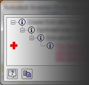
 in the QAT (Quick Access Toolbar). Click the red cross to use the Design Doctor. More information about the Design Doctor is included later in this topic.
-
Error dialog box displaying a hierarchical list leading to the error and a red cross. From this dialog box you can start the Recover (Design Doctor) process or resolve the error without assistance.
Design Doctor
The Design Doctor tracks design errors and provides recovery guidance. The goal is to help detect design problems that occur as you work and provide paths to correct the problems. To work with Design Doctor, see Use Design Doctor to repair relationship errors.
When unresolved errors occur in a model, a red cross appears on the Quick Access toolbar or in the message dialog. You can click the red cross to open the Design Doctor where you begin the recover process.
At any time you can close the window to stop using Design Doctor and proceed to resolve issues without guidance. Or, return later and use the Recover option in the browser node context menu.
To suppress Design Doctor error messages, see Prompts Tab Reference (Application Options).
Drawings
Edit RVT Errors
If editing a simplified RVT "future" file there may be options and settings used in making the Simplified model that do not exist in the opening Inventor version. A warning message reports: "This Revit model was created using an unsupported value for the 'Structure' option." The most likely explanation is that this file was created in a future ("dot") version of Inventor." The command is cancelled.
The message may occur if there is an invalid value for the Structure setting. The command is cancelled.
To resolve the issue the compatible release is needed. Install the compatible Inventor version and open the model.
Error Reporting
You can send error reports directly to Autodesk when software closes unexpectedly. You can determine who receives notification when reported errors are resolved. When reporting errors provide as much detail as needed to explain the workflow being used when the software closed.
It may be helpful to copy error messages to the clipboard when possible. With the dialog box active, use "Alt + Print Screen" to capture an image of the dialog box and place it on the clipboard. Paste the captured image into the error report or include it as an attachment.
File Open Errors
If you encounter an issue related to opening a file, start the troubleshooting process here.
- Error: Inventor can't open this file because it was saved in a newer version of Inventor.
- Error: Inventor is not able to detect VBA on your system.
- Error: Inventor doesn't recognize the format of this file (RSe stream error).
- Network connectivity issues can affect your ability to open files. When errors occur check that the network location is accessible.
File Save Errors
File Save errors can occur when there is a network connectivity issue preventing Inventor from reaching a server. When errors occur check that the network location is accessible. This can also occur this when the disk space is full.
iLogic
Imported Data Errors
Installation
See AKN (Autodesk Knowledge Network) topics pertaining to Troubleshooting Installation Issues.
Mold Design
- Error report dialog boxes in mold design
- Perform cooling channel check
- Generate Core and Cavity - to analyze the model for errors, see Edit a core cavity in this topic.
Part Errors
- The specified fillet radius is larger than the size of the adjacent face.
- Too many edges are being filleted at one time. For more information about fillets see To Create Edge Fillets.
- The profile/direction for a cut extrusion doesn't remove material from the body or bodies.
- To Find Relationships in Part - relates to diagnosing part feature relationships.
- To Work with the Thread Data Spreadsheet - relates to customizing thread designations.
- To Overwrite or Version Legacy Material Libraries - relates to errors when managing Material Libraries.
- Tolerance Advisor Messages - relates to the error messages encountered when defining 3D annotations.
When the message dialog box displays an error list, the design failures display in red underlined text. If you select a design failure message in the list, the location of the failure highlights in the graphics window.
Because you can choose to accept errors and proceed, Inventor also provides Design Doctor and Sketch Doctor to help find design errors in parts, sketches, drawings, and assemblies.
Project Files
If you have not previously worked with Inventor Project files we strongly recommend reviewing the following information before you start a design. See About Project Files
See
Roll Back History
In Part models rolling back the history can help locate where a potential error occurred. To roll back the history:
- Do either of the following:
- Find the End of Part (or End of Feature) symbol at the bottom of the browser, and drag it up to “roll back” the model.
- Right-click a feature in the browser and select Move EOP Marker to move the EOP marker to that feature.
This temporarily removes the features below the EOP symbol from the model. This can be useful as you troubleshoot the model by moving the marker down one feature at a time until the errant feature is discovered. Then, analyze the reason for the error.
- To update the model, drag the symbol back to the bottom of the browser, or right-click the EOP marker and select Move EOP to End.
If an error occurs during the process, a message box displays an error list. The error occurred because the change affected a feature or one of its references and it fails to resolve the rebuild. Expand the levels in the message to reveal the root cause for the failure.
If it is not clear why the error occurred, move the EOP marker back to the point where the change was made. Then, move the marker down the browser one node at a time until the error occurs, then determine the cause for the error.
Routed Systems
- Correct imported harness data
- Set splice length
- About bend radius checking
- Control display and occurrence order for looms - relates to loom ID errors
Cable and Harness
- Bend Radius Checks
Tube and Pipe
Sheet Metal
Flat Pattern Errors may occur when editing and updating the model. A dialog box indicates any error conditions that exist in the flat pattern. You can accept and continue working, although the error warnings persist until the error conditions are eliminated.
Intersecting Features (such as flange features that overlap in the flat pattern) may prevent the model from unfolding. A warning dialog box indicates intersecting features. You can Edit or Cancel the dialog box, or you can Accept the intersecting errors. If you accept, the flat pattern is developed with intersecting features. Subsequent feature creation in the folded model displays the dialog box until you edit the features that intersect in the flattened state.
- For more on Sheet Metal design see About Sheet Metal Flat Patterns
- To Work with Sheet Metal Punch Tools - If you attempt to save a sheet metal punch iFeature that contains no centermarks, an error message advises you to edit the sketch to add the centermarks.
Sketch Doctor
Sketches form the basis of most model features. Finding an error in a sketch requires that you understand the relationships among all of the pieces of sketch geometry. Also, be aware of how you plan to use the sketch to create subsequent model features.
The Sketch Doctor, part of the Design Doctor, can help you find overlapping curves, redundant points, missing coincident constraints, self-intersecting and open loops. Issues involving incorrect angles or dimensions require closer scrutiny.
Dimensional sketch constraints allow you to use formulas that include parameters. If there are parameter syntax errors, the text is red in the edit field. Correct the error and continue.
- Edit the sketch where the error occurs.
- In the browser, right-click the sketch node and click Sketch Doctor.
- In the Sketch Doctor dialog, click Diagnose Sketch.
- Specify the tests to apply to the sketch and click OK to run the diagnosis.
- The error(s) display in the Sketch Doctor and is highlighted in the display. If more than one error occurs, you can select each error in the dialog and see the error highlighted in the corresponding area in the display.
- Click Next to see the next step for resolving the error.
If your sketch includes imported geometry that another designer created, identifying design errors can be challenging. Common issues include the following:
- Imported geometry that appears to define a closed region can have small gaps between lines and arcs. These gaps prevent the region from behaving as expected during the creation of a solid feature.
- Lines that appear to be perpendicular do not actually measure 90 degrees. This issue might not become apparent until you attempt to assemble the part.
- Imported sketches sometimes cause unexpected behavior because of the way the geometry was created in the exporting system.
The Sketch Doctor, part of the Design Doctor, can help you find problems with overlapping curves, redundant points, missing coincident constraints, self-intersecting and open loops. Issues involving incorrect angles or dimensions require closer scrutiny. Dimensional sketch constraints allow you to use formulas that include parameters. If there are parameter syntax errors, the text is red in the edit field. Correct the error and continue.
Sketches and Sketch Dimensions
Sketch Dimension Precision
If you use formulas in sketch dimensions you may have experienced a result where a dimension has a very small value that is not visible in the rounded value seen in the edit field. For example, you might see a dimension such as 0.37500004 in display as 0.375 or 9.52500004 mm display as 9.525. In the status bar, click the dimension
Value
 list and select
Precise Value
list and select
Precise Value
 . Adjust dimensions that are not conforming to your intention.
Offset value does not match your input
When creating an offset you input a value and the result is imprecise. Check whether or not Snap to Grid is turned on. If On, turn it Off. It is likely that Snap to Grid is causing the imprecise result by enforcing the use of a nearby grid point.
Driven (Reference) Dimensions
- Changing another dimension to a Driven dimension
- Removing or relaxing geometric constraints. For example, removing a perpendicular constraint will allow a line to change angles relative to the line it is perpendicular to.
Task Scheduler
- Log File Reference - for more on Task Scheduler error messages
- To Export Task Errors to Excel - export error messages to an Excel spreadsheet