
Wireframe swarf finishing creates a swarf toolpath from two profile curves. PartMaker creates a toolpath cutting with the side of the tool as the tool follows the two curves (a top and bottom curve). As with swarf machining, you must be able to create a developable surface from the two curves. For more information, see Swarf machining.
To specify the profile curves you want to use as the top and bottom swarfing curves, double-click on a profile in the CAM Face window to display the Curve Properties dialog.
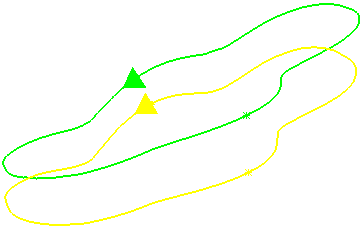
It is important to ensure that the curves are in the same direction.

To change the direction of a curve, select the curve in the CAM Face window and select Edit > Reverse.
This strategy supports Top Swarfing and Bottom Swarfing curves.
This strategy is available only for the Mill 5-Axis Plane machining function in PartMaker/SwissCAM, PartMaker/Turn-Mill and PartMaker/Mill.
On the Strategy dialog, the following pages are available for the Wireframe swarf finishing strategy:
- Wireframe swarf finishing — The main page used to define a wireframe swarf toolpath.
- Position — Settings todetermine the location of the toolpath.
- Gouge avoidance — Settings to determine what happens to the toolpath when a surface prevents machining at the lowest position.
- Multiple cuts — Settings to enable multiple passes down the tool axis.
- High speed — Settings to improve the smoothness of the toolpath.
The remaining pages are common toolpath creation controls.