
Distort Menu Settings
Distort Settings
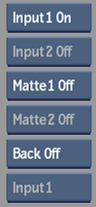
Input1 Display box
Select a display mode for Input1.
Input2 Display box
Select a display mode for Input2.
Matte1 Display box
Select a display mode for Matte1.
Matte2 Display box
Select a display mode for Matte2.
Back Display box
Select a display mode for the background clip.
Input box
Toggles between Input1 and Input2 clips based on the selection in the View box.
If Input is selected in the View box, this box toggles between Front1 and Front2. If Matte is selected in the View box, this box toggles between Matte1 and Matte2. If Result is selected in the View box, this box toggles between showing the splines for Front1 and Front2 drawn on top of the result.
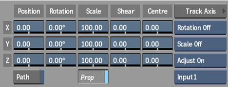
X Position field
Displays the position of the X axis. Editable.
Y Position field
Displays the position of the Y axis. Editable.
Z Position field
Displays the position of the Z axis. Editable.
Motion Path button
Enable to animate the position of the axis using a spline drawn in the scene.
X Rotation field
Displays the rotation value of the X axis. Editable.
Y Rotation field
Displays the rotation value of the Y axis. Editable.
Z Rotation field
Displays the rotation value of the Z axis.
X Scale field
Displays the scale value of the X axis. Editable.
Y Scale field
Displays the scale value of the Y axis. Editable.
Z Scale field
Displays the scale value of the Z axis. Editable.
Prop Scale button
Enable to scale the X, Y, and Z axes proportionally.
X Shear field
Displays the shear value of the X axis. Editable.
Y Shear field
Displays the shear value of the Y axis. Editable.
Z Shear field
Displays the shear value of the Z axis. Editable.
X Centre field
Displays the centre value of the X axis. Editable.
Y Centre field
Displays the centre value of the Y axis. Editable.
Z Centre field
Displays the centre value of the Z axis. Editable.
Track Axis button
Opens the Stabilizer menu to apply tracking data to an axis.
Tracking Rotation box
Select whether tracking rotation is On, Off, or Inverted.
Tracking Scale box
Select whether tracking scaling is On, Off, or Inverted.
Tracking Adjust box
Select whether an offset is applied relative to the spline's axis.
Track Clip box
Select the clip to track.
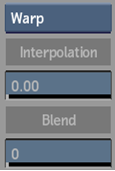
Warper button
Select whether to display the Warp or Morph menu.
Interpolation field
Displays the percentage of mixing between the Input1 spline and the Input2 spline when source splines are linked for source interpolation. Editable.
You independently set an interpolation value for each set of linked Front1 and Front2 source splines.
Blend field
Displays the level of blend between the Input1 and Input2 clips when morphing. Editable.
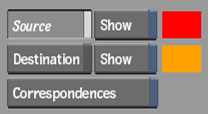
Source button
Enable to display source splines for manipulation. Also use to display the unwarped input clip.
Source Show button
Enable to display source splines for reference when working with destination splines.
Source colour pot
Displays the colour of all source splines. Editable.
Destination button
Enable to display destination splines for manipulation. Also use to display the warped input clip.
Destination Show button
Enable to display destination splines for reference when working with source splines.
Destination colour pot
Displays the colour of all destination splines. Editable.
Correspondences button
Enable to display correspondence points and connector lines, which indicate how the source spline maps to the destination spline.
You can add, edit, animate, and delete correspondence points. The more correspondence points a spline has, the greater effect it has on the overall warp.
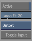
Active button
Enable to allow greater control over an animated spline by toggling selected vertices on and off.
Lasso Fit field
Displays the number of vertices in freehand segments of a spline. Editable.
Increasing the value decreases the number of vertices, while decreasing the value increases the number of vertices. Only segments of the spline drawn using freehand mode are affected, while segments created by simple clicks remain unaffected. The Lasso Fit parameter loses its influence over freehand segments of a spline if you edit vertices.
Link box
Controls whether source and destination splines are linked together or manipulated independently.
Set this to Lnk Src & Dst to keep the source and destination splines linked as you draw and animate the source spline. Set this to Enable Warping to control the destination spline independently to create a warp. You can also independently link and unlink the axis nodes that are the parents of a source spline and its corresponding destination spline.
Toggle Input button
Switch between an Input1 spline and an Input2 spline.
This is useful when you have animated a spline on one input and wish to apply it to the other.
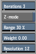
Iterations field
Displays a value for the distance that the distortion follows the destination spline. Editable.
If Z-mode is disabled, the maximum distance of the distortion is limited to avoid overlapping. When there is a large distance between a source and destination spline, you will achieve better results by increasing the number of iterations. For smaller warps or morphs, there is no advantage in using a greater number of iterations—it will increase processing time unnecessarily.
Z-mode button
Enable to allow overlapping in the image to create 3D-like effects where parts of the image are pulled over other parts.
Range field
Displays the size of the region affected by the warping effect. Editable.
The greater the value, the larger the portion of the image affected. A value of 100% affects the entire image, a value of 33% affects one-third of the image, for example.
Weight field
Displays the relative weight on the selected spline, to control its influence. Editable.
For example, you can set a higher weight on a spline in an area of the image that you do not want to move.
Resolution field
Displays the pixel resolution of the clip being warped or morphed. A lower pixel resolution creates warps and morphs that better follow the contours of the distortion splines, although it can slow down system performance.
Track Shape button
Opens the Stabilizer menu to apply tracking data to a spline's vertices.
Adjust box
Select whether an offset is applied relative to the spline's tangents.
Distort Setup Settings
Repeat button
Enable to fill in gaps by repeating the clip.
Repeat Value box
Select 4 to fill gaps by repeating the clip once on each side, or 8 to repeat the clip twice on each side.
Amount box
Select the amount of clip to repeat.
Draw Grid button
Enable to display the distortion grid.
Scale Setup button
Enable to scale a loaded setup's splines to the resolution of the current project.
Icons button
Enable to display splines, tangents, and vertices in the image.
Icons Transparency field
Displays the transparency level of the icons in the image. Editable.
Tangent colour pot
Displays the colour of tangents on the splines. Editable.
Schematic Transparency field
Displays the transparency level of the schematic. Editable.
Undo Levels field
Displays the levels of Undo available in the Undo/Redo lists. Editable.
Miscellaneous Settings
Exit button
Exits the Distort module.
Load button
Loads a setup.
Save button
Saves a setup.
Setup Name field
Displays the name of the last saved setup.
Revert button
Reverts to the last saved setup.
Player button
Opens the Player to view the last rendered clip.
Step Process field
Displays the frame number interval to be processed (to see intermediate results, for example). Editable.
Preview button
Displays the distort effect without processing.
Setup button
Opens the Setup menu, where you can set various preference and display settings.
Animation button
Opens the channel editor, where you can animate various distort settings.
Set Key button
Sets a keyframe at the selected frame.
Delete Key button
Deletes the selected keyframe.
Copy button
Copies an object, a branch (object and its children), or all, depending on what is selected in the Selection Mode box.
Delete button
Deletes an object, a branch (object and its children), or all, depending on what is selected in the Selection Mode box.
Selection Mode box
Select whether to copy, delete, or reset.
Reset button
Resets an object, a branch (object and its children), or all, depending on what is selected in the Selection Mode box.
Node Name field
Displays the name of the selected node in the schematic. Editable.
Previous button
Selects the previous node in the schematic.
Next button
Selects the next node in the schematic.
Add button
Adds an axis or spline, depending of the selection of the Node box.
Node box
Select whether to add an axis or spline, then click Add.
Close button
Closes a spline at the first vertex.
Finish button
Finishes a single-point or open spline at the last vertex.