TSD functionality is only available if the TSD option is enabled on your licence.
TVD Connectors can be used to provide a link between data streams in a Scalar TSD object and a Regulator. The data stream profiles can be used as an input to the connected regulator object to control the regulator either directly or indirectly.
Direct control of regulators
TVD connectors can be set up to use data streams from a TSD to model a regulator under manual control. To use TVD connectors to directly control the status of a regulator:
- Set the connected object to be the regulator link (using the TVD Connector Connected object type and Connected object id fields).
- Set Connection usage to Input
- Set Input attribute to the appropriate control type
The values provided by the time series data streams are used to control the regulator and will replace RTC controls for the regulator if RTC is present. RTC, if available, will be used at timesteps where the output from the time series data streams is null.
Note that the Output units type field must be set correctly before an Input attribute can be selected, as only input attributes that match the selected unit type are displayed.
Regulator output units
The output units required for different regulator types are listed below:
| Regulator type | Regulated variable | Unit type |
|---|---|---|
| All pumps | On - off | |
| Variable speed pump | Discharge |
Q - Flow |
| Variable frequency drive pump | Speed |
WN_AV - Rotation speed |
| Variable limiting discharge orifice | Maximum discharge |
Q - Flow |
| Variable crest weir | Crest level |
Z - Height above datum |
| Variable width weir | Width |
L - Length |
| Variable height gate (sluice gate or penstock) | Vertical opening | Z - Height above datum |
| Variable radial sluice | Opening (in degrees) |
ANGLE - Angle |
Direct control example
The following example uses direct control to set telemetry values for the height of a sluice gate during the observed period and then falls back to RTC to determine height during the forecast period.
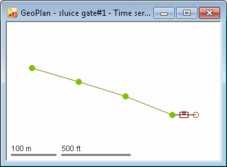
-
Set up an observed data stream, sluice_height, to control the height of the sluice gate during the observed period.

-
Set up a second data stream, use_rtc, containing one null value at a time before the simulation is to start.

-
Set up a TVD connector linking the data streams to the sluice. Set Input units type to L and Input attribute to INPOPENING. Set Input A to #sluice_height i.e. the values read from the datastream connected to telemetry and Input B to #use_rtc i.e. the null value. Input B will be used when there are no data values for Input A.
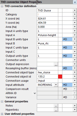
The input to the TVD connector is a series of telemetry values from Input A until the end of the observed period, followed by a series of null values until the end of the run. These values are used as an input to control the sluice gate opening. The null values tell the simulation engine to use RTC.
Indirect control of regulators
TVD connectors can be set up to use data streams from TSD objects to indirectly control a regulator. The data streams provide the values to be used in RTC Tables.
To use data streams from TSD objects to indirectly control the status of a regulator via RTC:
- Set the Connected object type field of the TVD connector to hw_rtc
- Set the Connected object id field to the relevant RTC table. The reference should take the form RegulatorID.TableName for tables defined in regulators in the RTC, or TableName for tables defined in the Global section of the RTC.
- Set the Input attribute field to INPRTCOUT
The values provided by the time series data streams are used to replace the referenced table values.
Indirect control example
The following example shows how to adapt RTC control to use indirect control to set telemetry values for the height of a sluice gate, falling back to RTC when telemetry values are not available.

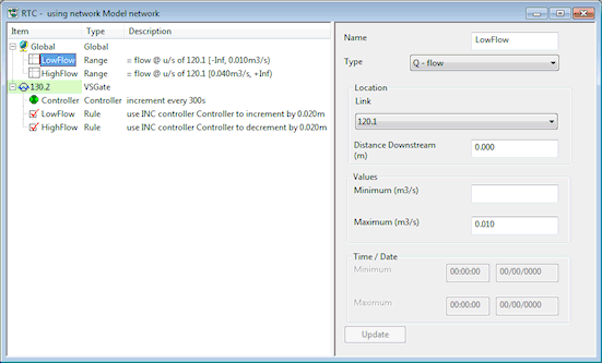
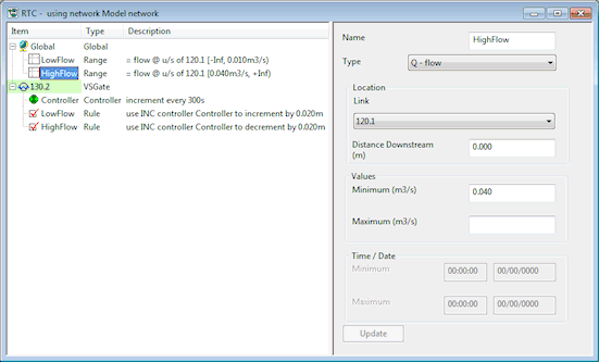
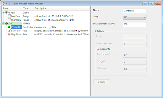
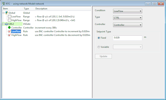
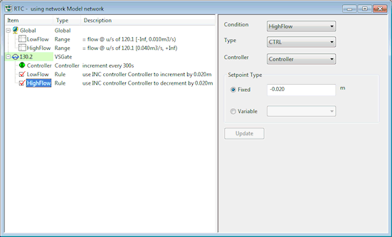
The table below displays the details of the RTC components required to control the flow through the sluice gate by using an incremental controller to control the setting of the sluice gate opening.
The steps required to use telemetry data to control sluice gate opening are described below.
|
Component |
Name |
Parameters |
Effect |
|---|---|---|---|
|
RANGE 1 |
LowFlow |
Range type: Q - flow Location link: 120.1 Minimum: Maximum: 0.010 |
Defines Link 120.1 as a control conduit with a maximum value of 0.010 m3/s
|
|
RANGE 2 |
HighFlow |
Range type: Q - flow Location link: 120.1 Minimum: 0.040 Maximum: |
Defines Link 120.1 as a control conduit with a minimum value of 0.040 m3/s
|
| CONTROLLER | Controller |
Type: INC Measurement Interval: 300 |
Defines that REGULATOR increments should be carried out every 300 s
|
|
RULE 1 |
LowFlow |
Condition: LowFlow Type: CTRL Controller: Controller Fixed: 0.020 m |
If the flow in Link 120.1 is less than 0.010 m3/s, increment sluice gate setting by 0.02 m
|
| RULE 2 | HighFlow |
Condition: HighFlow Type: CTRL Controller: Controller Fixed: -0.020m |
If the flow in Link 120.1 is more than or equal to 0.040 m3/s. decrements sluice gate setting by 0.02 m
|
Using TSD data streams to control sluice gate opening
To use telemetry values where available to control sluice gate opening, falling back on the original RTC rules when there are no telemetry values:
-
Set up an observed data stream, sluice_height, to control the height of the sluice gate when there are data stream values available.

-
Set up a second data stream, use_rtc_indirect, containing a value of -999, for example, at a time before the simulation is to start. Do not set a Data interval.

-
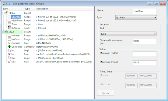
Edit the RTC so that the sluice_height data stream is used when values are available and the original RTC rules are used when a value of -999 is encountered.
Component
Name Parameters
Effect
RANGE 1
LowFlow Range type: Q - flow
Location link: 120.1
Minimum:
Maximum: 0.010
Defines Link 120.1 as a control conduit with a maximum value of 0.010 m3/s (as original RTC)
RANGE 2
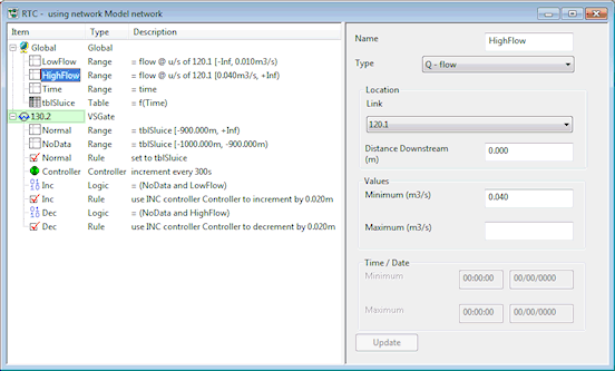
HighFlow Range type: Q - flow
Location link: 120.1
Minimum: 0.040
Maximum:
Defines Link 120.1 as a control conduit with a minimum value of 0.040 m3/s (as original RTC)
RANGE 3 Time Range type: T-time Time range to be used as input to Sluice opening table
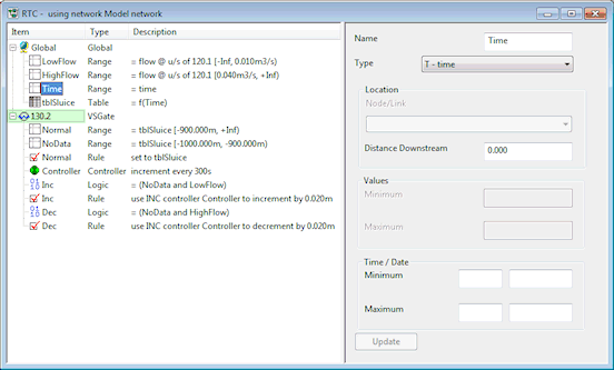
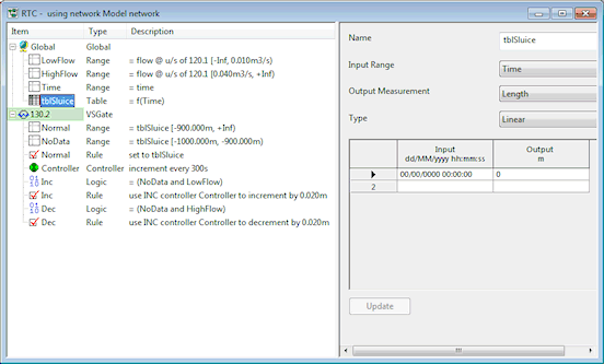
TABLE 1 tblSluice Input Range: Time
Output Measurement: Length
Type: Linear
Input/Output grid: Time vs Length
Defines the relationship between time of simulation and the opening of the sluice gate. The records in the table will be supplied by the sluice_height or use_rtc_indirect data streams set up in Step 1 and Step 2.
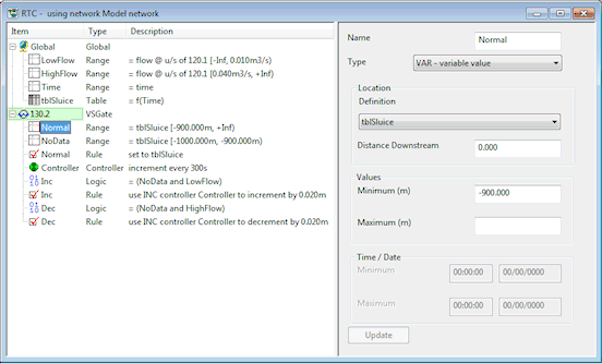
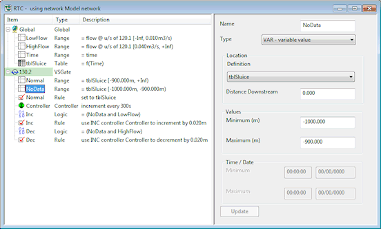
RANGE 4 Normal Range type: VAR- variable value
Location Definition: tblSluice (TABLE 1)
Minimum: -900 m
Defines a normal range where values provided for tblSluice by the TVD connector are greater than -900. (This will be when values are available from data stream sluice_height.)
RANGE 5 NoData Range type: VAR - variable value
Location Definition: tblSluice (TABLE 1)
Minimum: -1000.000 m
Maximum: -900.000 m
Defines an erroneous range where values provided for tblSluice by the TVD Connector are between -1000 and -900. (This will be when values are not available from data stream sluice_height and are provided by data stream use_rtc_indirect.)
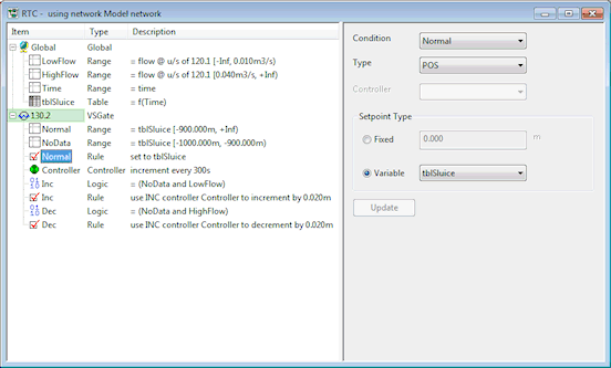
RULE 1 Normal Condition: Normal (RANGE 4)
Type: POS
Setpoint Variable: tblSluice (TABLE 1)
If the tblSluice values provided by the data streams are greater than -900, the sluice opening will be controlled by tblSluice.
(Data stream sluice_height values will control the sluice opening)
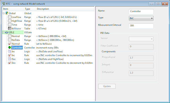
CONTROLLER Controller Type: INC
Measurement Interval: 300
Defines that REGULATOR increments should be carried out every 300 s (as original RTC)
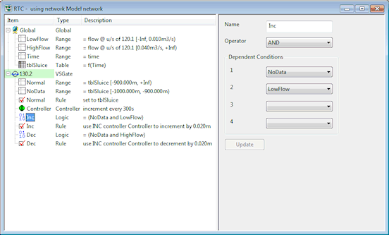
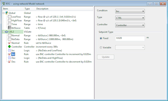
LOGIC 1 Inc Operator: AND
Condition 1: NoData (RANGE 5)
Condition 2: LowFLow (Range 1)
Check for tblSluice values in the NoData range and flow in Link 120.1 less than 0.01 m3/s
RULE 2
Inc Condition: Inc (LOGIC 1)
Type: CTRL
Controller: Controller
Fixed: 0.020 m
If tblSluice values provided by data streams are in the NoData range and the flow in Link 120.1 is less than 0.010 m3/s, increment sluice gate setting by 0.02 m
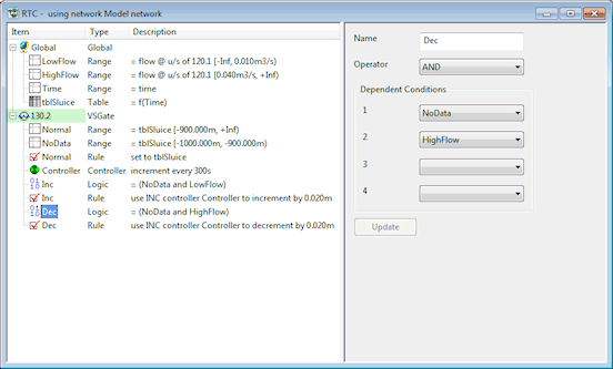
LOGIC 2 Dec Operator: AND
Condition 1: NoData (RANGE 5)
Condition 2: HighFLow (Range 2)
Check for tblSluice values in the NoData range and flow in Link 120.1 more than than 0.01 m3/s
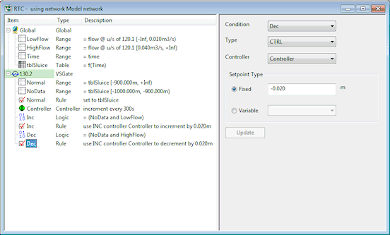
RULE 3 Dec Condition: Dec (LOGIC 2)
Type: CTRL
Controller: Controller
Fixed: -0.020m
If tblSluice values provided by the data streams are in the NoData range and the flow in Link 120.1 is more than 0.040 m3/s. decrements sluice gate setting by 0.02 m
- Set up a TVD connector linking the data streams to the RTC table.
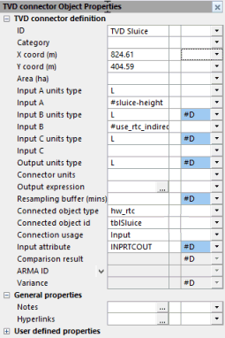
- Input units type: set to L
- Input A: set to #sluice_height i.e. the values read from the datastream connected to telemetry
- Input B: set to #use_rtc_indirect i.e. the -999 value. Input B will be used when there are no data values for Input A.
- Connected object type: set to hw_rtc
- Connected object id: set to tblSluice (the dropdown contains a list of RTC tables)
- Input attribute: set to INPRTCOUT
The input to the TVD connector is a series of telemetry values from Input A. When there are no values from Input A, the -999.0 value from Input B will be used. These values are used as an input to tblSluice in the RTC control.
When there are Input A values available, the Input A data stream values will be used to control the sluice gate opening via the RTC table tblSluice.
When the values from Input B are used, the original RTC control rules will be used to control the sluice gate.

