Change Option Settings
Options settings control the number of points included in the laser projection data. More points create a more accurate representation of the geometry to be projected. However, too many points can cause the image to flicker. Reducing the number of points will help to reduce flicker; however, if the number of points is too small, you start to lose the original shape of the geometry to be projected.
Accessing Options
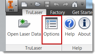
The Options location varies in the TruLaser ribbon based on whether you are starting up TruLaser:
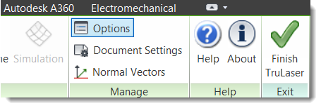
Or, are already viewing a laser data file:
Changing Options
Click on a settings area on the left to view the corresponding options on the right. If you make a change, click OK to save the new settings.
| General |
- Select Show tool tips on tree nodes to view brief descriptions of the tree elements as you hover your mouse pointer over the tree nodes.
- Select Show point-level nodes in tree to display the point nodes of a curve in the browser tree. If the laser data contains a lot of points and you do not need to work at the point level, you can deselect this option to improve performance. For example, if refreshing the tree takes time, deselecting this option might refresh the tree faster.
- Enter a value and select a unit of measure to automatically display for normal vectors.
As part of the TruLaser installation, a basic set of projector stands, projectors, targets, and tools are stored in the directory shown and automatically included in your projects for easy access. Although you cannot change this path, you can add equipment of your own to the library folder.
|
| Projector |
- Select the projector type to automatically use when adding a new projector to a laser project. This should be the projector type that you use most often. This setting does not prevent you from choosing a different type when placing a projector.
- Select the preferred incidence angle quality (good, acceptable, bad) color indicator by clicking the current color and selecting from the palette. These settings also appear in the Color settings.
- Enter the angle values that define a good and acceptable incidence angle.
- Click in the box next to the obstructed object field to set the color to display if a laser line is blocked.
- Click in the box next to the projector FOV field to set the color to display if an object is not in a projector's field of view. This could indicate that a projector needs to be adjusted to include the object.
|
| Geometry |
These settings control the number of points included in the laser projection data. More points result in a more accurate representation of the geometry to be projected. However, too many points result in the image beginning to flicker. Fewer points will help to reduce this flicker, but if there are too few points, you start to lose the original shape of the geometry to be projected.
- Enter a chordal tolerance value and select a unit of measure. Chordal tolerance indicates the amount of sag allowed in the line replicating a curve. If, despite this setting, a line sags too much, you can add a point in the middle of the line to control the accuracy of the laser data.
- Enter a length tolerance value and select a unit of measure. This value indicated at what increments points should be placed along a line; if a point doesn't exist at that increment, TruLaser adds one.
- Enter a default tolerance, which controls the number of points included on a curve. Because a laser projector cannot project a curve, spline, or circle, the curved areas must be tessellated to show an approximation of the curved area. The tolerance value controls how tight the approximated laser data follows the original curved area. In general, a larger value for tolerance results in fewer points that represent the curved area, while a smaller value for tolerance results in more points being used to represent the curved area. For example, if you choose 1cm for the tolerance, then the straight-line segments that approximate the curved area will be allowed to sag up to 1cm away from the original curved geometry.
- Enter a default shortest laser segment length to control the number of points included on all laser geometry (straight lines or curved areas). The shortest value removes points in areas where there are too many points, resulting in image flickering. For example, consider a straight segment that is 1 meter in length between two points. If the shortest segment value is equal to or greater than 1 meter, then the second point will be removed on the straight segment. If the value is anything less than 1 meter, then no changes will be made to the 1 meter long segment.
- Enter a default longest laser segment length to force additional points in areas where there are not enough points to accurately represent the original geometry (straight lines or curved areas). The longest value forces additional points in areas where there are not enough points to accurately represent the original geometry. For example, consider a straight segment that is 1 meter in length between two points. If the shortest segment value is equal to or greater than 1 meter, then no points will be added to the existing straight segment. If the value is anything less than 1 meter, then at least one point will be added in the center of the 1 meter long segment.
|
