
Boundary Heat Flux Load
Description: Defines a uniform heat flux into a set of grid points.
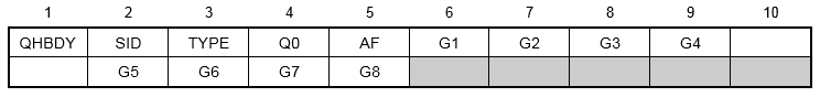
Format:
Example:

| Field | Definition | Type | Default |
|---|---|---|---|
| SID | Load set identification number. | Integer > 0 | Required |
| TYPE | Surface type, one of the following character variables: POINT, LINE, AREA3, AREA4, AREA6, or AREA8. See Remark 2. | Character | Required |
| Q0 | Magnitude of thermal flux into face. | Real | Required |
| AF | Area factor depends on type. | Real > 0.0 or blank | 0.0 |
| Gi | Grid point identification of connected grid points. | Integer > 0 or blank | Required |
Remarks:
- QHBDY entries must be selected with the Case Control command LOAD = SID in order to be used in steady state heat transfer analysis.
- The heat flux applied to the area is transformed to loads on the points. These points need not correspond to an HBDY surface element.
- The total power into each point i is given by the equation:
Pin = Areaj * Q0
- The number of connect points for the types are 1 (POINT), 2 (LINE), 3 (AREA3), 4 (AREA4), 4-6(AREA6), 5-8 (AREA8).
- The area factor AF is used to determine the effective area for the POINT and LINE types. It equals the area and effective width, respectively. It is not used for the other types, which have their area defined implicitly.
- The type of face (TYPE) defines a surface in the same manner as the CHBDYi data entry. For descriptions of the geometry involved, see the CHBDYG discussion.
- The continuation entry is optional.