
Gap Element Connection
Description: Defines a gap or friction element.
Format:

Example:

Alternate Format and Example:
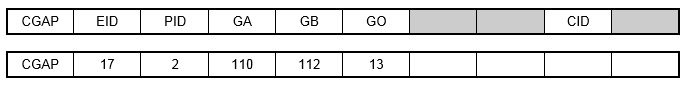
| Field | Definition | Type | Default |
|---|---|---|---|
| EID | Element identification number. | Integer > 0 | Required |
| PID | Property identification number of a PGAP entry. | Integer > 0 | Required |
| GA, GB | Grid point identification numbers of connection points. | Integer > 0; GA ≠ GB | Required |
| X1, X2, X3 | Components of vector
 , from GA, in the displacement coordinate system at GA (see Figure 1). , from GA, in the displacement coordinate system at GA (see Figure 1).
|
Real or blank | |
| G0 | Grid point identification number to optionally supply X1, X2, X3. Direction of orientation vector is GA to G0. | Integer or blank | |
| CID | Element coordinate system identification number. CID must be specified if GA and GB are coincident. See Remark 7. | Integer ≥ 0 or blank |
Remarks:
- The CGAP element is intended for use in nonlinear static analysis. It will produce a linear stiffness matrix for all other solutions. The stiffness used depends on the gap state.
- The gap element coordinate system is defined by one of two following methods:
- If the coordinate system (CID field) is specified, the element coordinate system is established using that coordinate system, in which the element x-axis is in the T1 direction and the y-axis in the T2 direction. The orientation vector
will be ignored in this case.
- If the CID field is blank and the grid points GA and GB are not coincident, then the line AB is the element x-axis and the orientation vector
lies in the x-y plane.
- If the coordinate system (CID field) is specified, the element coordinate system is established using that coordinate system, in which the element x-axis is in the T1 direction and the y-axis in the T2 direction. The orientation vector
- The element coordinate system does not rotate as a result of deflections.
- Initial gap openings are defined on the PGAP entry and not by the separation distance between GA and GB.
- Forces, which are requested with the STRESS Case Control command, are output in the element coordinate system. Fx is positive for compression.
- This element will default to a linear spring in linear solutions including linear static analysis with linear contact enabled. A nonlinear solution must be selected for general contact behavior.
- If CID is being used to define the element coordinate system and the CID refers to either a cylindrical or spherical coordinate system, then grid GA will be used to locate the system. If grid GA lies on the z-axis of the cylindrical or spherical coordinate system, it is recommended that a different coordinate system be used to define the element orientation.
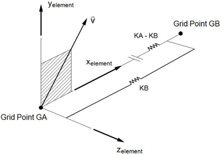
Figure 1. CGAP Element Coordinate System