
Milling Direction List
Description: Defines a list of milling directions for 5-axis milling manufacturing constraints in design optimization analysis.
Format:
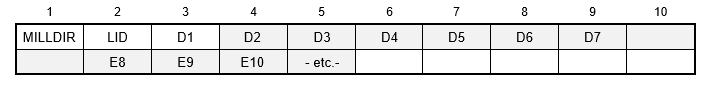
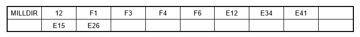
Example:
| Field | Definition | Type | Default |
|---|---|---|---|
| LID | List identification number. | Integer > 0 | Required |
| Di | Direction symbols. See Remarks 1 and 2. | Character | Required |
Remarks:
- At least one direction symbol is required. Specifying all 26 is equivalent to the default setting for 5-axis milling when a milling direction list is not specified on the TOPVAR Bulk Data entry.
- The following table lists all 26 possible milling directions. C symbols are for corner directions, F symbols are for face directions, and E symbols are for edge directions. The cube shown in Figure 1 represents the voxelized model with a bounding box with corners numbered from 1 - 8. The milling directions are in the manufacturing coordinate system defined on the TOPVAR Bulk Data entry.
| Direction Symbol | X Component | Y Component | Z Component |
|---|---|---|---|
| C1 | 1.0 | 1.0 | 1.0 |
| C2 | –1.0 | 1.0 | 1.0 |
| C3 | –1.0 | –1.0 | 1.0 |
| C4 | 1.0 | –1.0 | 1.0 |
| C5 | 1.0 | 1.0 | –1.0 |
| C6 | –1.0 | 1.0 | –1.0 |
| C7 | –1.0 | –1.0 | –1.0 |
| C8 | 1.0 | –1.0 | –1.0 |
| F1 | 1.0 | 0.0 | 0.0 |
| F2 | 0.0 | –1.0 | 0.0 |
| F3 | 0.0 | 0.0 | –1.0 |
| F4 | –1.0 | 0.0 | 0.0 |
| F5 | 0.0 | 1.0 | 0.0 |
| F6 | 0.0 | 0.0 | 1.0 |
| E12 | 0.0 | 1.0 | 1.0 |
| E23 | –1.0 | 0.0 | 1.0 |
| E34 | 0.0 | –1.0 | 1.0 |
| E41 | 1.0 | 0.0 | 1.0 |
| E56 | 0.0 | 1.0 | –1.0 |
| E67 | –1.0 | 0.0 | –1.0 |
| E78 | 0.0 | –1.0 | –1.0 |
| E85 | 1.0 | 0.0 | –1.0 |
| E15 | 1.0 | 1.0 | 0.0 |
| E26 | –1.0 | 1.0 | 0.0 |
| E37 | –1.0 | –1.0 | 0.0 |
| E48 | 1.0 | –1.0 | 0.0 |
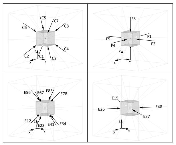
Figure 1: Milling Direction Symbol Definitions