
Solid Element Orthotropic Material Property Definition
Description: Defines the material property for an orthotropic material for isoparametric solid elements.
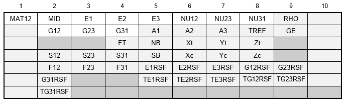
Format:
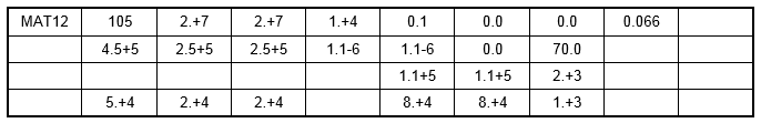
Example:
| Field | Definition | Type | Default | ||||||||||
|---|---|---|---|---|---|---|---|---|---|---|---|---|---|
| MID | Material identification number. Referenced on a PSHELL or PCOMP entry only. | Integer > 0 | Required | ||||||||||
| E1 | Modulus of elasticity in longitudinal direction, also defined as the fiber direction or 1-direction. | Real > 0.0 | Required | ||||||||||
| E2 | Modulus of elasticity in lateral direction, also defined as the matrix direction or 2-direction. | Real > 0.0 | Required | ||||||||||
| E3 | Modulus of elasticity in thickness direction, also defined as the matrix direction or 3-direction. | Real > 0.0 | Required | ||||||||||
| NU12 | Poisson's ratio (-ε2/ε1 for uniaxial loading in 1-direction). Note that
 for uniaxial loading in 2-direction is related to for uniaxial loading in 2-direction is related to
 , E 1, and E 2 by the relation , E 1, and E 2 by the relation
 . See Remark 3. . See Remark 3.
|
Real | Required | ||||||||||
| NU23 | Poisson's ratio (-ε3/ε2 for uniaxial loading in 2-direction). Note that
 for uniaxial loading in 3-direction is related to for uniaxial loading in 3-direction is related to
 , E 2, and E 3 by the relation , E 2, and E 3 by the relation
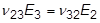 . See Remark 3. . See Remark 3.
|
Real | Required | ||||||||||
| NU31 | Poisson's ratio (-ε1/ε3 for uniaxial loading in 3-direction). Note that
 for uniaxial loading in 1-direction is related to for uniaxial loading in 1-direction is related to
 , E 1, and E 3 by the relation , E 1, and E 3 by the relation
 . See Remark 3. . See Remark 3.
|
Real | Required | ||||||||||
| RHO | Mass density. | Real or blank | 0.0 | ||||||||||
| G12 | Shear modulus in plane 1-2. | Real > 0.0 | Required | ||||||||||
| G23 | Shear modulus in plane 2-3. | Real > 0.0 | Required | ||||||||||
| G31 | Shear modulus in plane 3-1. | Real > 0.0 | Required | ||||||||||
| Ai | Thermal expansion coefficient in i-direction. | Real or blank | 0.0 | ||||||||||
| TREF | Reference temperature for the calculation of thermal loads. | Real or blank | 0.0 | ||||||||||
| GE | Structural element damping coefficient. See Remarks 9, 10, and 12. | Real or blank | 0.0 | ||||||||||
| FT | Composite failure theory. The following theories are allowed:
|
Character or blank | |||||||||||
| NB | Allowable inter-laminar normal stress of the composite laminate bonding material (allowable interlaminar normal stress). See Remark 14. | Real ≥ 0.0 or blank | See Remark 14 | ||||||||||
| Xt, Xc | Allowable stresses or strains in tension and compression, respectively, in the longitudinal direction. Required if composite element failure index is desired. | Real ≥ 0.0 or blank | Default value for Xc is Xt | ||||||||||
| Yt, Yc | Allowable stresses or strains in tension and compression, respectively, in the lateral direction. Required if composite element failure index is desired. | Real ≥ 0.0 or blank | Default value for Yc is Yt | ||||||||||
| Zt, Zc | Allowable stresses or strains in tension and compression, respectively, in the thickness direction. Required if composite element failure index is desired. | Real ≥ 0.0 or blank | Default value for Zc is Zt | ||||||||||
| S12 | Allowable shear stress or strain for plane 1-2. | Real ≥ 0.0 or blank | 0.0 | ||||||||||
| S23 | Allowable shear stress or strain for plane 2-3. | Real ≥ 0.0 or blank | 0.0 | ||||||||||
| S31 | Allowable shear stress or strain for plane 3-1. | Real ≥ 0.0 or blank | 0.0 | ||||||||||
| F12 | Interaction term in the tensor polynomial theory of Tsai-Wu. Required if composite element failure index by Tsai-Wu theory is desired and if value of F12 is different from 0.0. See Remark 13. | Real | 0.0 | ||||||||||
| F23 | Interaction term in the tensor polynomial theory of Tsai-Wu. Required if composite element failure index by Tsai-Wu theory is desired and if value of F23 is different from 0.0. | Real | 0.0 | ||||||||||
| F31 | Interaction term in the tensor polynomial theory of Tsai-Wu. Required if composite element failure index by Tsai-Wu theory is desired and if value of F31 is different from 0.0. | Real | 0.0 | ||||||||||
| SB | Allowable inter-laminar shear stress of the composite laminate bonding material (allowable interlaminar shear stress). See Remark 15. | Real ≥ 0.0 or blank | See Remark 15 | ||||||||||
| E1RSF | Longitudinal (1-direction) modulus of elasticity reduction scale factor for nonlinear composite Progressive Ply Failure Analysis (PPFA). See Remark 16. | 0.0 ≤ Real ≤ 1.0 | 1.0 | ||||||||||
| E2RSF | Lateral (2-direction) modulus of elasticity reduction scale factor for nonlinear composite Progressive Ply Failure Analysis (PPFA). See Remark 16. | 0.0 ≤ Real ≤ 1.0 | 1.0 | ||||||||||
| E3RSF | Through thickness (3-direction) modulus of elasticity reduction scale factor for nonlinear composite Progressive Ply Failure Analysis (PPFA). See Remark 16. | 0.0 ≤ Real ≤ 1.0 | 1.0 | ||||||||||
| G12RSF | Plane 1-2 shear modulus reduction scale factor for nonlinear composite Progressive Ply Failure Analysis (PPFA). See Remark 16. | 0.0 ≤ Real ≤ 1.0 | 1.0 | ||||||||||
| G23RSF | Plane 2-3 shear modulus reduction scale factor for nonlinear composite Progressive Ply Failure Analysis (PPFA). See Remark 16. | 0.0 ≤ Real ≤ 1.0 | G12RSF | ||||||||||
| G31RSF | Plane 3-1 shear modulus reduction scale factor for nonlinear composite Progressive Ply Failure Analysis (PPFA). See Remark 16. | 0.0 ≤ Real ≤ 1.0 | G12RSF | ||||||||||
| TE1RSF | Identification number of a TABLES1 or TABLEST entry which defines the stress-strain relationship in the longitudinal direction for nonlinear composite Progressive Ply Failure Analysis (PPFA). | Integer ≥ 0 or blank | |||||||||||
| TE2RSF | Identification number of a TABLES1 or TABLEST entry which defines the stress-strain relationship in the lateral direction for nonlinear composite Progressive Ply Failure Analysis (PPFA). | Integer ≥ 0 or blank | |||||||||||
| TE3RSF | Identification number of a TABLES1 or TABLEST entry which defines the stress-strain relationship in the thickness direction for nonlinear composite Progressive Ply Failure Analysis (PPFA). | Integer ≥ 0 or blank | |||||||||||
| TG12RSF | Identification number of a TABLES1 or TABLEST entry which defines the stress-strain relationship in the 1-2 plane for nonlinear composite Progressive Ply Failure Analysis (PPFA). | Integer ≥ 0 or blank | |||||||||||
| TG23RSF | Identification number of a TABLES1 or TABLEST entry which defines the stress-strain relationship in the 2-3 plane for nonlinear composite Progressive Ply Failure Analysis (PPFA). | Integer ≥ 0 or blank | TG12RSF | ||||||||||
| TG31RSF | Identification number of a TABLES1 or TABLEST entry which defines the stress-strain relationship in the 3-1 plane for nonlinear composite Progressive Ply Failure Analysis (PPFA). | Integer ≥ 0 or blank | TG12RSF |
Remarks:
- The material identification number must be unique for all MATi entries.
- An approximate value for G23 and G31 is the in-plane shear modulus G12. If test data is not available to accurately determine G23 and G31, the value to G12 may be supplied for G23 and G31.
- Material stability requires that


If either condition is not met, a warning message will be issued.
- It may be difficult to find all nine orthotropic constants. In some practical problems, the material properties may be reduced to normal anisotropy in which the material is isotropic in a plane (i.e., plane 1-2) and has different properties in the direction normal to this plane. In the plane of isotropy, the properties are reduced to

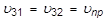
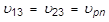
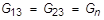
with
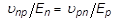 and
and

There are five independent material constants for normal anisotropy (i.e.,
 ,
,
 ,
,
 ,
,
 , and
, and
 ). In case the material has a planar anisotropy, in which the material is orthotropic only in a plane, the elastic constants are reduced to seven (i.e.,
 ,
,
 ,
,
 ,
,
 ,
,
 ,
,
 , and
, and
 ).
).
- Xt, Yt, Zt, S12, S23, and S31 are required for composite element failure calculations when requested in the FT field of the PCOMP entry. Xc, Yc, and Zc are also used but not required.
- MAT12 materials may be made temperature-dependent by use of the MATT12 entry. In STATIC solutions, linear elastic material properties will be updated as prescribed under the TEMPERATURE Case Control command.
- The mass density, RHO, will be used to automatically compute mass for all structural elements.
- Weight density may be used in field 9 if the value 1/g is entered on the PARAM, WTMASS entry, where g is the acceleration of gravity.
- To obtain the damping coefficient GE, multiply the critical damping ratio C/C0, by 2.0.
- TREF and GE are ignored if the MAT12 entry is referenced by a PCOMP entry.
- TREF is used only as the reference temperature for the calculation of thermal loads in linear solutions. If TEMPERATURE(INITIAL) is specified, TREF will be ignored.
- If PARAM, W4 is not specified, GE is ignored in transient response analysis. (See Section 5, Parameters, for more information on W4.)
- The interaction terms F12, F23, and F31 are experimentally determined from test specimens under multiaxial loading. This inconvenience along with the constraint that F12, F23, and F31 satisfy stability criteria of the form
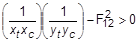
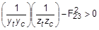
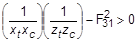
creates complications in the use of this theory. For this reason it is recommended that F12, F23, and F31 be set to zero
- The allowable inter-laminar normal stress value NB corresponds to the top surface of the ply. The default value for NB is defined in the NB field of the PCOMPS entry and will be used when this field is blank.
- The allowable inter-laminar shear stress value SB corresponds to the top surface of the ply. The default value for SB is defined in the SB field of the PCOMP, PCOMPG, and PCOMPS entries and will be used when this field is blank.
- Recommended values for E1RSF, E2RSF, E3RSF, G12RSF, G23RSF, and G31RSF are shown in the below table.
Variable Recommended Value E1RSF 0.04 E2RSF 0.04 E3RSF 0.04 G12RSF 0.20 G23RSF 0.20 G31RSF 0.20