
Use the Mill Cylinder Options dialog to control the tool's Y coordinate for the Mill Cylinder Face window.
To display this dialog, click the Mill Cylinder Options button in the Profile Group Parameters dialog - Milling.
The following settings are available:
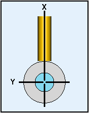
Radial Tool — When this option is selected, the tool is always radial; that is, the axis of the tool is always perfectly aligned with the axis of rotation of the stock. With this option, the toolpath can be programmed either at the bigger or the smaller cylinder diameter and the Y-coordinate of the center of the tool is always zero.
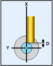
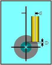
Radial Walls — When this option is selected, PartMaker calculates the Y-coordinate of the tool at every point such that the wall of the contour machined by the tool is always radial; that is, the wall of the contour is always perfectly aligned with the axis of the rotating stock. With this option, the toolpath has to be programmed at the smaller cylinder diameter. The depth of cut D is usually set to 0, except in the case of hollow tubing, when a small value of D might have to be added for the tool to be able to break through the tube. The Z_Rapid and Z_Clear are then used to move the tool in and out of the stock.
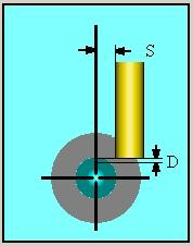
Constant Distance — When this option is selected, the Y-coordinate of the tool at every point is calculated such that the axis of the tool is always at a constant distance from the axis of the rotating stock.
You can use specify a constant distance that is Perpendicular or Along Y Axis. In both these cases, the toolpath has to be programmed at the smaller cylinder diameter. The depth of cut D is usually set to 0, except in the case of hollow tubing, when a small value of D might have to be added for the tool to be able to break through the tube. The Z_Rapid and Z_Clear are then used to move the Tool into and out of the Stock.
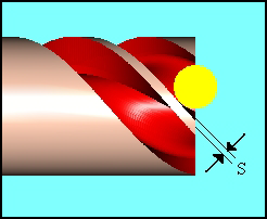
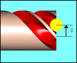
- Perpendicular — With this option, the tool is always positioned perpendicular to the toolpath at the distance you specify in the Distance field and the Y-coordinate of the tool is calculated for each toolpath point.
When using this option, the Tool Position must be set to Left or Right.
Distance.
When using a Perpendicular Constant Distance, this value represents the distance of the tool from the axis of the rotating stock perpendicular to the toolpath. This must be a positive value.
- Along Y Axis — With this option, every toolpath point is assigned a constant Y-coordinate, equal to the distance you specify in the Distance field.
When using this option, the Tool Position must be set to On.
Distance
When using a Constant Distance Along Y Axis, this value represents the constant Y-coordinate of the tool for every toolpath point. You can specify a positive or a negative value.