
Use the Components Properties dialog to identify the different types of components in a setup assembly and specify how each component is displayed in the Solids window.
To display this dialog:
- Select ToolMinder > Setup Assembly > Component Properties; or
- Double-click on a component in the Solids window when in Setup Assembly mode.
To use this dialog:
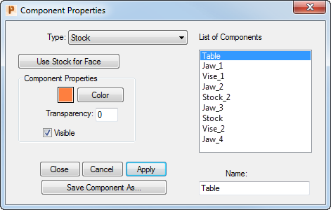
- Select the component you want to work with from the List of Components. If you double-clicked a component in the Solids window to display this dialog, PartMaker automatically selects this component in the list.
- PartMaker gives default names to the components in the setup assembly. To use a different name, enter a new name in the Name field.
- You can specify the following settings for the selected component:
Type — Specify whether the component represents a Fixture, Stock or Table.
Use Stock for Face — For Stock components, click this button to display the Use Stock For Face dialog, where you can select the Face window that uses this stock component.
Component Properties — These options control how the component appears in the Solids window:
- Color — Click to display the Color dialog, where you can select the color of the component.
- Transparency — Specify the transparency for the component. 0% displays a solid component. 100% displays a fully transparent (invisible) component.
- Visible — Select this option to display the component in the Solids window.
- Click Close to apply any changes and close the dialog.
Tip: Use the Save Component As button to save the selected component to a separate X_T Parasolid Transmit file, so you can use it with other setup assemblies.