
Use the Curve Info – Line dialog to display geometric information about the currently selected curve-type line.
To display this dialog, double-click a line edge on a solid model.
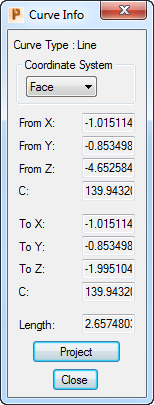
The following settings are available:
Coordinate System — Select an option to specify whether the coordinates are measured relative to the Part or Face coordinate system.
From X, From Y, From Z — These fields display the X, Y and Z coordinates of the start point of the line.
C — Displays the C angle of the start point of the line.
To X, To Y, To Z — These fields display the X, Y and Z coordinates of the end point of the line.
C — Displays the C angle of the end point of the line.
Project — Click to project the selected edge onto the current PartMaker Face window. PartMaker displays the Convert Curved Edges dialog for you to choose how to convert the curved edges.
PartMaker projects the outline in a direction perpendicular to the Face Plane of the current Face window. (For 5-axis Faces, this will be the inclined plane.)