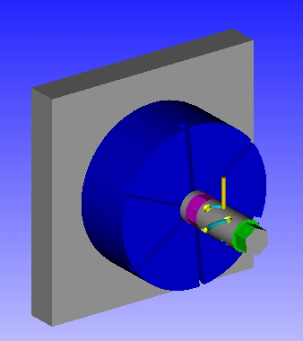
Use the Table Settings dialog to define the dimensions and appearance of a 4-axis rotary table on a milling machine.
To display this dialog, click Settings on the Setup dialog and select Rotary 4 Axis from the Table Type list.
The following settings are available:
Table Type — Select a table type. The dialog changes to reflect the table selected.
Work Holding Location — Select the location of the work holding (Left or Right).
Length (L) — Enter the length of the table.
Width (W) — Enter the width of the table.
Height (H) — Enter the height of the table.
Stock Extension (E) — Enter the length of stock section that protrudes from the chuck or other fixture. PartMaker uses this value for collision checking during simulation. This value is not required if you are using a setup assembly.
Indexing Time (min) — Enter the average Rotary 4-Axis table index time.
Chuck
Use Chuck — Select if you are using chuck on the table.
Chuck Data — When a chuck is used, click this button to display the Chuck Data dialog where you can specify details about the chuck.
Simulation Settings
Table Transparency — Enter the transparency of the table when displayed in the Simulation window, where 0% displays a solid table and 100% displays a fully transparent (invisible) table.
Table Color — Click to display the Color dialog, where you can specify the color of the table during simulation.
Machine File — Click this button to display the Machine File dialog, which enables you to import settings from a machine file or export settings to a machine file.
Programming tips
You can display the rotary table in simulation by modifying the chuck data:
- Select the Use Chuck option on this dialog.
- In the Chuck Data dialog, set Jaw Transparency to 100%.
