When using PartMaker/SwissCAM, the following options are available on the Set Modes dialog:
Main Spindle Mode
Specify how the main spindle machines the process:
- Idle (MO) — Select if the main spindle is not used during machining.
- Machining with One Tool (M1) — Select if the main spindle uses one tool during machining.
- Machining with Two Tools (M2) — Select if the main spindle uses two tools during machining.
Sub-Spindle Mode
Specify how the sub-spindle machines the process:
- Idle (S0) — Select if the sub-spindle is not used during machining.
- Follow Support (SF) — Select if the sub-spindle supports the stock during machining. The sub-spindle collet is closed during machining. Using this mode, the sub-spindle moves in synchronization with the main spindle.
Note: Select this option, together with Cutting With One Tool (M1) for the main spindle, for cut-off processes (M1SF).
- Non-Follow Support (SN) — Select if the sub-spindle supports the stock during machining. The sub-spindle collet is open during machining, which provides extra support during machining.
- Machining with One Tool (S1) — Select if the sub-spindle uses one tool during machining.
- Machining with Two Tools (S2) — Select if the sub-spindle uses two tools during machining.
- Double-Ended Drilling (SD) — Select if the main and the sub-spindle perform double-ended drilling or on-centerline drilling simultaneously.
Graphical representation of Synchronization Mode
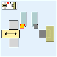
The top right-hand area of the dialog contains a graphical representation of the Synchronization Mode, which updates to reflect your selections for Main Spindle Mode and Sub-Spindle Mode.
The tool in use during the process is shown in yellow. The tool that is not cutting is shown in gray. For example:

Other options
The following options are also available:
- Modify Mode for Current Process Only — Select this option to apply your selections to the current process only.
- Modify Modes for all Consecutive Processes with Same Mode — Select this option to apply your selections to all consecutive processes with the same Synchronization Mode.
- Eject Part (E) — Select this option to eject the part from the sub-spindle at the end of the process. You would usually select this option for the last process machined on the sub-spindle. You can set this option automatically for the last process on the sub-spindle, by selecting the Eject Part After Last Sub-Spindle Process option on the Process Table Options dialog.
- Sub-Spindle Support Z-Coordinate (Sz) — When the Sub-Spindle Mode is:
- Follow Support (SF), enter the Z position at which the sub-spindle grips the part.
- Non-Follow Support (SF), enter the distance between the main spindle and the sub-spindle during support.
- Sub-Spindle Z-Distance from Home — Enter the machining position of a sub-spindle relative to its home position. This is available for the
M0S1,
M1S1,
M0S2,
M1S2, or
M2S1 Synchronization Modes for processes programmed on the sub-spindle.
This option is available only if the postprocessor uses the <sub-spindle-distance> reserved word.
- Stock Motion — Click to display the Stock Motion dialog, where you can specify whether the stock or the tool moves in the Z axis.
This button is not available for processes in Faces that are machined on the sub-spindle or for Material Control Processes (MCPs).
- Wait Distances — Click to display the Wait Distances dialog, where you can specify when the secondary tool and/or sub-spindle engages. This button is available only if the postprocessor supports wait distances.
User Data — Click to display the User Data dialog, where you can specify custom data (known as User Data) for the current Post Configuration file.