
When using the Profile Group Parameters dialog to set parameters for a Contour Mill strategy, the following settings are available:
Tool Position — Set the position of tool in relation to the profile: On, Left or Right.
Edge Machining — If the Tool Position is set to Left or Right, you can choose whether you want to machine the profile edge for deburring or other purposes: Select:
- None to leave the edge unmachined.
- Chamfering or Corner Rounding to machine the edge.
Toolpath Direction — Select the direction of the tool when machining the toolpath:
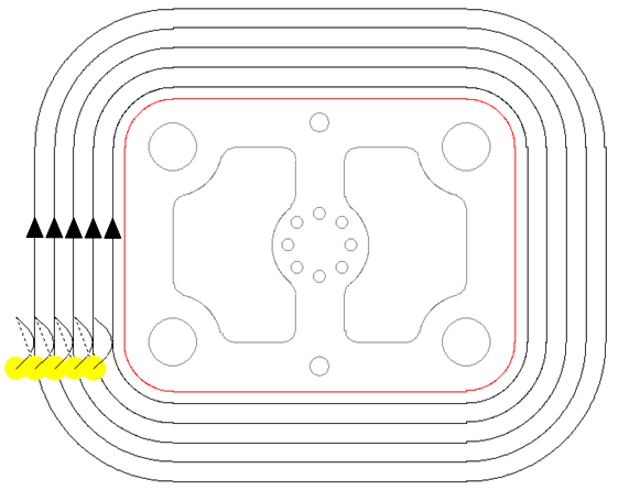
- Uni-Directional — Select this option so the tool performs a rapid move to the Rapid Plane after each pass of the toolpath before starting the next pass in the same direction.
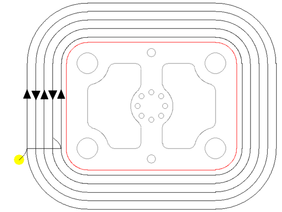
- Bi-Directional — Select this option so the tool does not retract to the Rapid Plane between passes. Instead, the tool completes one pass of the toolpath in one direction, before starting the next pass in the reverse direction.
Axial Step Control — Select whether or not the tool retracts to the start position between axial steps.
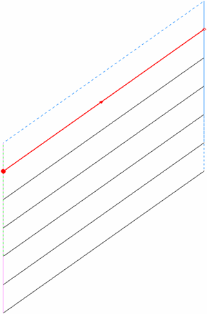
- Return to Start Point — Select this option so the tool retracts to the start position before the next axial step.
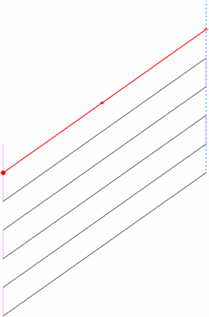
- Stay at Depth — Select this option so the tool stays at depth without retracting until the final depth is reached.
Chamfer(c) — Enter the horizontal length of the chamfer. This option is available only when Chamfering is selected for Edge Machining.
Z_Surf (S) — Enter the signed distance from the zero reference point to the part surface.
Z_Depth (D) — Enter the depth of the operation to be performed.
Z_Rapid (R) — Enter the distance between the bottom tip of the tool and the part surface when a tool performs rapid moves.
Z_Clear (Cl) — Enter the distance between the bottom tip of the tool and the part surface when a tool starts feeding into the part.
Bottom Finish (b) — Enter the amount of material left on the bottom for finishing if the Finishing option is selected.
Wall Finish (w) — Enter the amount of material left on the wall for finishing if the Finishing option is selected.
Initial Stock (q) — Enter the thickness of the initial stock to be contoured.
Operations information
- Roughing — Select this option to include a roughing pass operation.
- Finishing — Select this option to include the finishing pass operation.
- Chamfering — PartMaker automatically selects this option when Chamfering is selected as the Edge Machining operation. This creates a chamfering toolpath, based on the group profile curve. PartMaker calculates the depth of the toolpath based on the selected tool and the Chamfer (c) value. Chamfer tools, spot drills and regular drills can be used for this type of operation.
- Corner Rounding — PartMaker automatically selects this option when Corner Rounding is selected as the Edge Machining operation. This creates a corner-rounding toolpath, based on the group profile curve. PartMaker calculates the depth of the toolpath based on the selected tool. Only corner-rounding tools can be used for this type of operation.
- Diam (d) — Enter the diameter of the tool used to perform the selected operations, for example Roughing and Finishing operations.
- Tool ID — Enter the ID of the selected tool. When you have saved the group, you can click the icon showing a representation of the tool (for example
 ) to display the Edit Tool dialog to view, or modify, details of the tool.
 - Width of Cut — Enter the width of the cut for the operation. This value can be calculated as a percentage of the diameter of the tool selected for the operation or specified as an absolute value, depending on the Width of Cut and Width of Cut Value settings on the Defaults for Milling dialog. This field is not used if Initial Stock is set to 0.
- Axial Step — Enter the axial step of the tool. By default, PartMaker uses the Axial Step value specified in the tool's properties in the Tools Data dialog. If the axial step is set to zero, the material is removed in a single axial step.
- Leads — Click
 to display the Leads dialog, where you can control the movement of the tool as it:
- Approaches the stock before starting a cutting move (Leads In). Leads In consist of an arc that is tangential to the start of the profile and a line tangential to this arc.
- Leaves the stock at the end of a cutting move (Leads Out). Leads Out consist of an arc that is tangential to the end of the profile and a line tangential to this arc.
PartMaker creates Lead In and Lead Out moves when a profile group is created.
Advanced Milling Toolpath (legacy) — Select this option if you want PartMaker to use Advanced Milling options when calculating the toolpath for this profile group. When this option is selected, the following buttons are available:
- High Speed — Click to display the High Speed Machining dialog to set up options for high-speed machining. These include options for trochoidal milling, toolpath smoothing, profile smoothing and stroke transition.
- Rest Area — Click to display the Rest Area Machining dialog to set up options for rest area machining. Rest area machining enables you to machine only that area within the profile boundary which has not been machined by the previous toolpath.
- Sloped Walls — Click to display the Sloped Walls Machining Options dialog. Use this dialog to set options related to the machining of sloped walls.
- Advanced Tool Entry —Click to display the Advanced Tool Entry dialog. Use this dialog to specify how the tool plunges into the material at the beginning of a cut when using an Advanced Milling toolpath.
Polar Style Output — Select this option to specify whether the NC program is in polar format. This allows for Posts to explicitly support machining without polar interpolation activated in the NC code. This option is available only when using a Mill End, Polar Face window.
- When selected, the post will typically output X and Y positions with polar interpolation activated.
- When deselected, the Post will typically output Radius and C-angle positions without polar interpolation.
Lock Toolpath —Select this option to lock the toolpath. When a toolpath is locked, PartMaker does not recalculate it even if its settings on the Profile Group Parameters dialog change. Deselecting this option unlocks the toolpath.
Tool Entry — Click to display the Tool Entry dialog. This button is available only when the Advanced Milling Toolpath option is not selected.
Group Name — Enter a name for the profile group.
Select Tools — Click to display the Select Tool dialog, where you can select the tool to use for machining.
Mill Cylinder Options — Click to display the Mill Cylinder Options dialog, where you can set tool offset options for cylindrical milling. This button is available only for the Mill Cylinder Face window.
Extract Parameters From Solid — Select this option to extract geometric information from the imported solid model and use this information to complete some of the fields on this dialog. When you have selected this option, select surfaces on the solid model and then click Extract to extract the geometric information. Press the Shift key to select more than one surface at a time. Click Undo to revert any values on the dialog that have been calculated by extracting geometric data from the solid model back to their original values.