
Use the Holder Data dialog to view, or change, information about a machine's tool holders to control how they are displayed during Full Machine Simulation. PartMaker stores the holders you define using this dialog in the current Machine Data File (.mch) file.
To display this dialog, click the Holder Data button on the Machine Data dialog or the Tool Assembly dialog.
The following settings are available:
Milling Holder — Select if you have a Milling Holder.
Turning Holder — Select if you have a Turning Holder.
Holder Definition — Select how you want to define the holder for the machine:
- Solid Model — Select this option to use a solid model to represent the holder. Click Holder Models to display the Set Holder Models dialog and select the model file you want to use.
- Parametric — Select this option to create a parametric representation of the holder from the values specified in the Parametric Dimensions area of the dialog.
Parametric Dimensions — If you are creating a parametric representation of the holder, specify the dimensions you want to use in these fields:
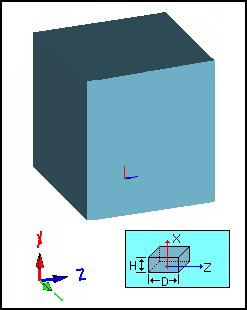
- Block — Specifies that a rectangular primitive is created, with its origin as shown below, when a parametric shape is chosen:
- H — The height dimension along the X-axis
- D — The width and depth of the base of the box.
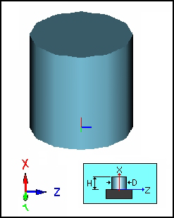
- Cylinder — Specifies that a cylindrical primitive is created, with its origin as shown below) when a parametric shape is chosen.
- H — The dimension height of the cylinder along the X-axis
- D — The dimension of the diameter for the cylinder.
Attachment Point and Direction (Holder to Tool Post)
- Holder Attachment Point (X, Y, Z) — Define the point where the holder attaches to a tool post. This point is defined in the Holder Coordinate System, see Attaching a tool to a holder for Full Machine Simulation for more information.
- Holder Attachment Direction — Select the axis that will align with a tool post location’s Holder Attachment Direction as specified in the Tool Post Layout dialog. This enables the holder to be rotated to the proper orientation when attached to the tool post. Typically this vector is perpendicular to a surface that will mount flush to a tool post. This axis is defined in the Holder Coordinate System, see Attaching a tool to a holder for Full Machine Simulation for more information.
 Set Attachment Point — Click to display the Attachment Information dialog, where you can specify the coordinates for the Attachment Point by clicking directly on the solid model. This button is available only if Solid Model is selected in the Holder Definition area of the dialog.
Attachment Point and Direction (Holder to Tool)
- Station ID — To enable a station, select the check box alongside it. There can be up to eight stations on a holder. You must enable stations in sequential order.
- Tool to Holder Attachment Point (X, Y, Z) — The position of the tool attachment on that specific station. The base of the tool attaches to this point. This point is defined in the Holder Coordinate System.
- Direction — Select the axis to which the tool aligns its shank before attaching to the tool. This axis is defined in the Holder Coordinate System.
 Set Attachment Point — Click to display the Attachment Information dialog, where you can specify coordinates for the Attachment Point by clicking directly on the solid model. This button is available only if Solid Model is selected in the Holder Definition area of the dialog.
Tool Extension Length — This is the length of a turning tool's shank that extends into the specified holder.
Units
- Metric — Select this option if the machine data uses metric units.
- Convert from Metric / Convert from Inch — Click this button to convert the holder data between Inch and Metric units.
Notes — Enter any additional information about the holder in this field.
Holder Orientation Angle — Specify the angle at which the holder model and its data will be rotated about the holder attachment orientation when viewed in simulation.
List of Holders — This area of the dialog lists the available holders. Details of the selected holder are displayed on the dialog.
New — Click to add a new holder by creating a copy of the holder that is selected in the List of Holders list box.
Delete — Click to delete the selected holder.
Holder Preview — Click to display a 3D preview of the holder data.